SYNTHESIZED
SWEEPER
ADAPTER
Q
SPECTRUM AN,
ALYZER
DIGITAL VOLTMETER
ADAPTER
jj
‘y.ln1111
A14>501
A14‘
FREO
CONTROL
A14J17
PIN
1
SK1 101
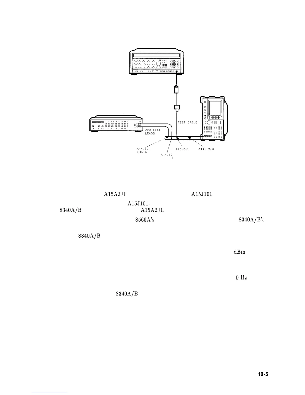
Figure 10-l. YTO Loop Test Setup
18. Disconnect W34 from
A15A2Jl
and disconnect W32 from
A15JlOl.
19. Connect a frequency counter to
A15JlOl.
Connect a high-frequency test cable from an
HP
8340A/B
Synthesized Sweeper to
A15A2Jl.
See Figure 10-2.
20. Connect a BNC cable from the HP
8560A’s
10 MHz REF IN/OUT to the HP 8340A/B’s
FREQUENCY STANDARD EXT input.
21. Set the HP
8340A/B
to the following settings:
FREQUENCY STANDARD. . . . . . . . . . . . . . . . . . . . . . . . . . . . . . . . . . . . . . . EXT
POWER LEVEL. . . . . . . . . . . . . . . . . . . . . . . . . . . . . . . . . . . . . . . . . . . . . .-5
dBm
FREQ STEP . . . . . . . . . . . . . . . . . . . . . . . . . . . . . . . . . . . . . . . . . . . . . . . . . . 7.5 MHz
22. Set the HP 8560A to the following settings:
SPAN. . . . . . . . . . . . . . . . . . . . . . . . . . . . . . . . . . . . . . . . . . . . . . . . . . . . . . . . . . .
OHz
CFSTEP . . . . . . . . . . . . . . . . . . . . . . . . . . . . . . . . . . . . . . . . . . . . . . . . . . . . . 7.5 MHz
23. Set the HP 8560A and HP
8340A/B
frequencies to the combinations listed in Table 10-2.
(Use the frequency step-keys on both instruments.)
Synthesizer Section
10-5