41. The Main Coil Coarse and Fine DACs correct any initial pretune errors in the YTO main
coil. The DACs adjust the FM-coil current to zero before any sweep begins. Refer to
function block I of Al4 Frequency Control Schematic (sheet 2 of 5).
42. Set the HP 8560A to the settings listed below. These set both
DACs to 128 (the DAC
setting range is 0 to 255).
CENTER FREQ. . . . . . . . . . . . . . . . . . . . . . . . . . . . . . . . . . . . . . . . . . . ...300 MHz
SPAN
. . . . . . . . . . . . . . . . . . . . . . . . . . . . . . . . . . . . . . . . . . . . . . . . . . . . . . . . . . .
OHz
TRIG
. . . . . . . . . . . . . . . . . . . . . . . . . . . . . . . . . . . . . . . . . . . . . . . . . . . . . . . . ..CONT
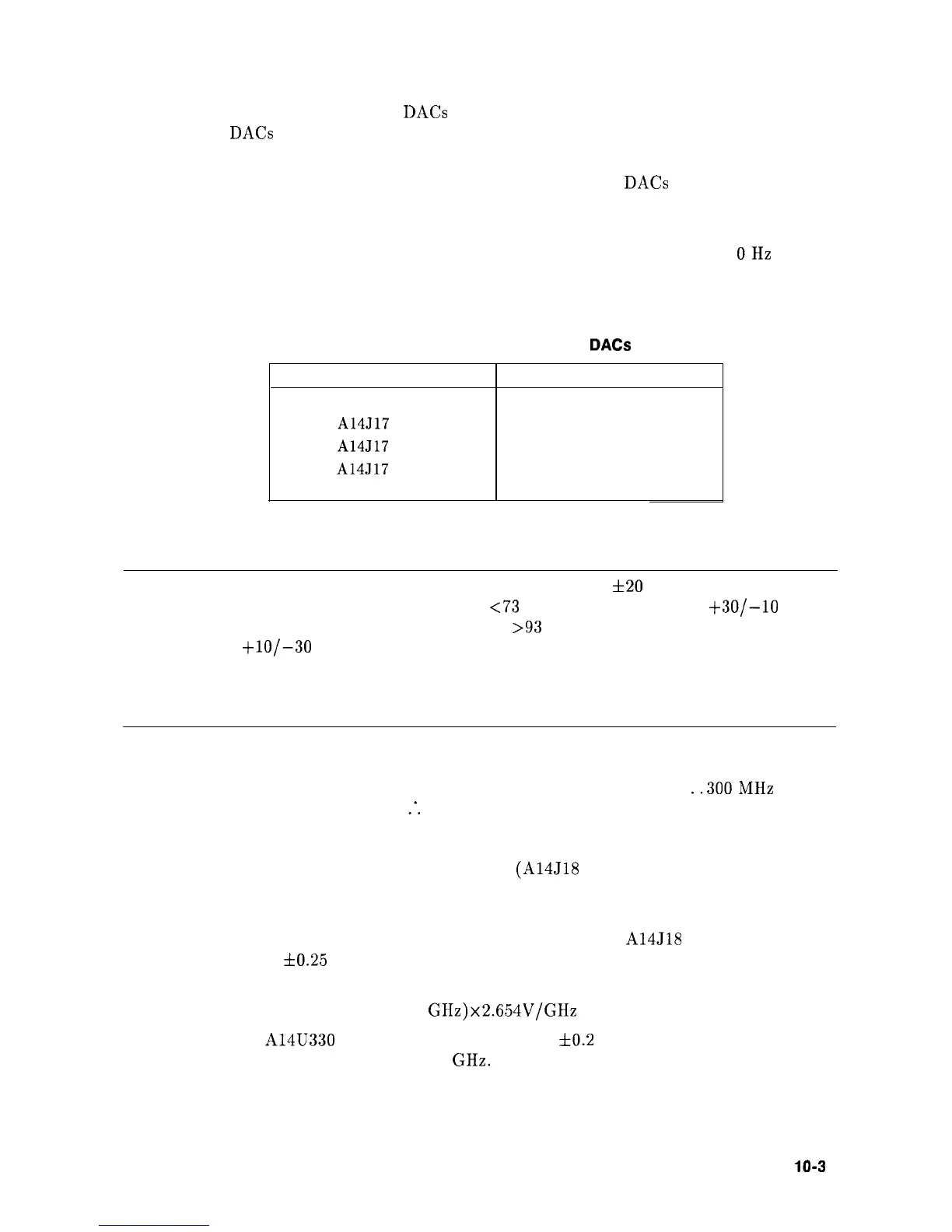
43. Verify the voltages listed in Table 10-14.
Table 10-14. Main Coil Coarse and Fine
DACs
Voltages
Measurement Points Voltages
A14J17 pin 2 -7.0 Vdc
A14J17 pin 3 -7.0 Vdc
A14J17 pin 5
+8.1 Vdc
44. Place jumper A14J23 in the NORMAL position.
Note
The All YTO has an initial pretune accuracy of
f20
MHz. However, when
the Roller Oscillator frequency is
<73
MHz this is changed to
+30/-10
MHz.
If the Roller Oscillator frequency is
>93
MHz, the accuracy is changed to
+lO/-30
MHz. This is done by changing the Main Coil Coarse DAC to keep
the Sampler IF within the acquisition range of the YTO Loop. When dealing
with the Sampler IF and an unlocked YTO, the same frequency differences
apply to the Sampler IF.
45. Set the HP 8560A to the following settings:
CENTER FREQ
. . . . . . . . . . . . . . . . . . . . . . . . . . . . . . . . . . . . . . . . . . . .
..300MHz
SPAN
. . . . . . . . . . . . . . . . . . . . .
:.
. . . . . . . . . . . . . . . . . . . . . . . . . . . . . . . . . . . . 0 Hz
46. Place jumper A14J23 in the TEST position.
47. Measure the output of the Main Coil Tune DAC
(A14J18 pin 3) with a DVM.
Refer to function block C of Al4 Frequency Control Schematic (sheet 2 of 5) in the
Component-Level Information binder.
48. If the HP 8560A’s center frequency is 300 MHz, the voltage at
A14J18 pin 3 should
measure -3.35 V
60.25
V. The voltage may also be determined from the following
equation:
V = -(lst LO Frequency-2.95
GHz)x2.654V/GHz
49. The voltage at A14U330 pin 2 should measure 3.4 V
f0.2
Vdc. This represents a current
setting the YTO to approximately 2.95 GHz.
Synthesizer Section
10-3 1