12. 10 MHz Reference Adjustment (Non-Option 003 only)
Assembly Adjusted
Al5 RF Assembly
Related Performance Test
10 MHz Reference Output Accuracy
Description
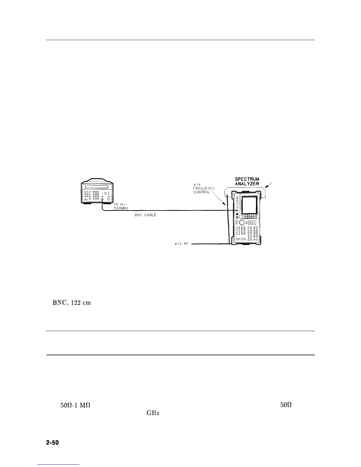
The frequency counter is connected to the CAL OUTPUT, which is locked to the 10 MHz
reference. This yields better effective resolution. The temperature-compensated crystal
oscillator (TCXO)
is adjusted for a frequency of 300 MHz as read by the frequency counter.
FREQUENCY COUNTER
PC
BOARD
PROP
Figure 2-15. 10 MHz Frequency Reference Adjustment Setup
Equipment
Microwave Frequency Counter
. . . . . . . . . . . . . . . . . . . . . . . . . . HP 5343A Option 001
Cables
BNC,122cm
(48in)
. . . . . . . . . . . . . . . . . . . . . . . . . . . . . . . . . . . . . . . . . . . . HP 10503A
Procedure
SK114
Note
Allow the HP 8560A to warm up for at least 30 minutes before performing
this adjustment.
1. Connect the equipment as shown in Figure 2-15. Prop up the Al4 Frequency Control
Assembly.
2. Set the HP 5343A controls as follows:
SAMPLE RATE . . . . . . . . . . . . . . . . . . . . . . . . . . . . . . . . . . . . . . . . . . . . . . . Midrange
5052-1Mfl SWITCH
. . . . . . . . . . . . . . . . . . . . . . . . . . . . . . . . . . . . . . . . . . . . . . . .
500
10 Hz-500 MHz/500 MHz-26.5 GHz SWITCH . . . . . . . . . . . . . . . . 10 Hz-500 MHz
2-50’
Adjustment Procedures