Procedure 7.
A6Al
High Voltage Assembly
16. Disconnect ribbon cable
A6AlWl
from
A6J5.
See Figure 3-11.
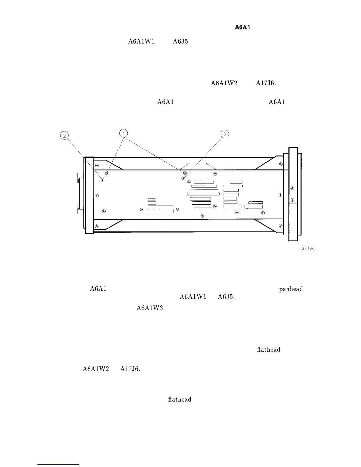
17. Remove the two screws (1) securing two board-mounting posts to the left side frame and
remove the posts. See Figure 3-13.
18. Remove the two left side-frame screws (2) securing the Al7 assembly.
19. Lift up the Al7 CRT driver assembly and disconnect
A6AlW2
from A17J6. Do not
remove any other cables from the Al 7 assembly.
20. Disconnect the tie wraps from the
A6Al
assembly cables and remove the
A6Al
High
Voltage assembly from the analyzer.
SK136
Figure 3-13. Al7 CRT Driver Mounting Screws
Replacement
1. Secure the
A6Al
High Voltage assembly to the A6 Power Supply using three
panhead
screws and washers. Connect ribbon cable
A6AlWl
to A6J5.
2. Snap post-accelerator cable
A6AlW3
to the CRT assembly.
3. Place the black grommet protecting the post-accelerator cable into the CRT shield.
4. Ensure that all cables are safely routed and will not be damaged when securing the A6
cover.
5. Secure the power supply cover shield to the power supply using three
flathead
screws (1).
See Figure 3-12. One end of the cover fits into a slot provided in the rear frame assembly.
6. Connect
A6AlW2
to A17J6.
7. Place the Al7 CRT Driver assembly into the center-deck mounting slot nearest the CRT.
Use caution when routing cables to avoid damage.
8. Secure the Al7 assembly with the two
flathead
screws removed in “Removal” step 17. See
Figure 3-13 (2).
9. Connect the two mounting posts to the left-side frame using the two screws removed in
“Removal” step 16. See Figure 3-13 (1).
Assembly Replacement 3-23