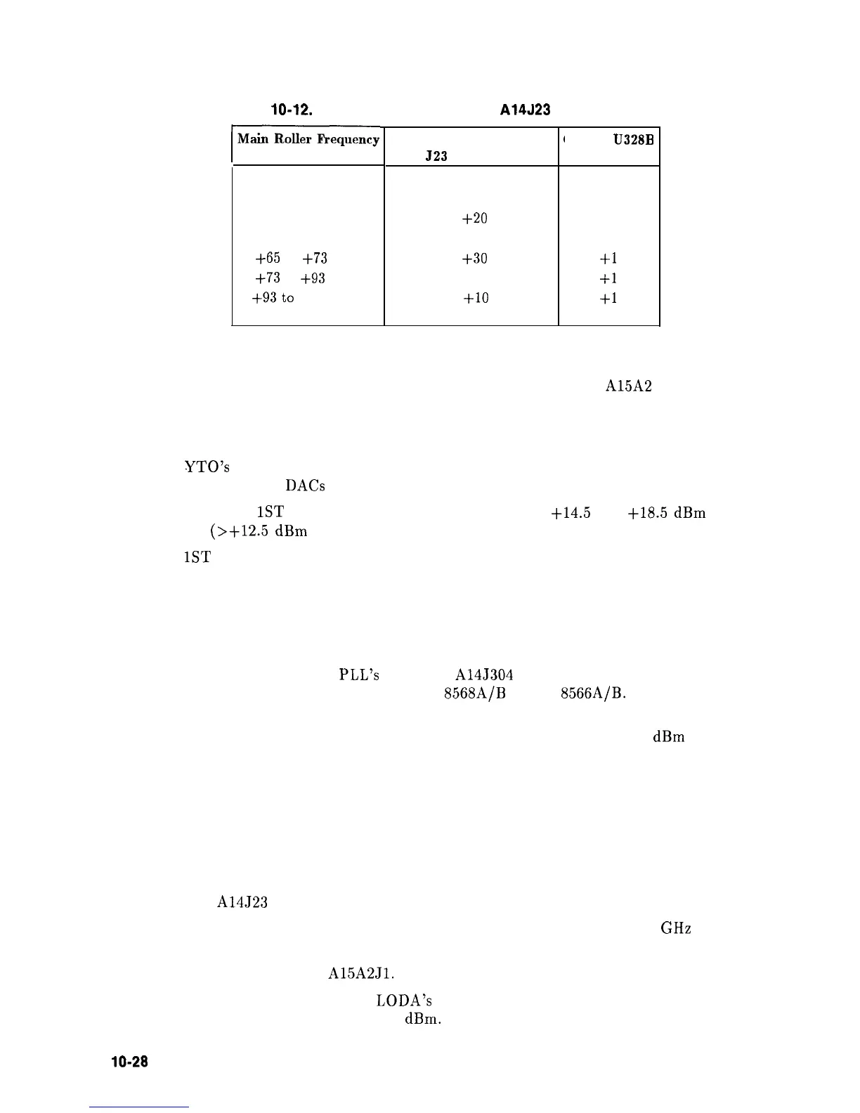
Table 10-12. YTO Frequency Errors with A14J23 on Pins 2 and 3
(
I
-104
to
-93
MHz
-93to-73
MHz
-73
to
-65
MHz
+65
to
+73
MHz
+73
to +93 MHz
+93to
$104 MHz
YTO Frequency Error
(with
523
on pins 2 and 3)
-10 to +30 MHz
-20
to +20 MHz
-30 to +10 MHz
-10
to +30 MHz
-20 to +20 MHz
-30
to
+lO
MHz
Gain of
U328B
-1
-1
-1
+1
$1
+1
10. The 1st LO’s pretuned frequency must be sufficiently accurate for the YTO loop to
acquire lock. The 1st LO’s amplitude must be sufficient to drive the
A15A2 Sampler.
Perform the YTO Adjustment procedure, particularly the YTO Main Coil adjustments.
(If available, use a synthesized microwave spectrum analyzer instead of the microwave
frequency counter specified in the adjustment procedure.)
11. If the
YTO’s main coil cannot be adjusted, proceed to step 33 to troubleshoot the Main
Coil Coarse and Fine DACs and Main Coil Tune DAC.
12. The front-panel’s
1ST
LO OUTPUT should measure between
t14.5
and
t18.5
dBm
in
amplitude.
(>+12.5
dBm
if Option 002 is present.)
13. If the
1ST
LO OUTPUT amplitude is out of the specified range, perform the First LO
Distribution Amplifier Adjustment procedure. Refer to Chapter 2.
14. Set the HP 8560A to the following settings:
CENTER FREQ
. . . . . . . . . . . . . . . . . . . . . . . . . . . . . . . . . . . . . . . . . . . ...300 MHz
SPAN
. . . . . . . . . . . . . . . . . . . . . . . . . . . . . . . . . . . . . . . . . . . . . . . . . . . . . . . . . . . 0 Hz
15. Monitor the Roller Oscillator
PLL’s output at A14J304 (ROLLER TST) with a
synthesized spectrum analyzer such as an HP
8568A/B
or HP
8566A/B.
Refer to function
block AQ of Al4 Frequency Control Schematic (sheet 5 of 5).
16. The signal at A14J304 (ROLLER TST) should
measure approximately -30
dBm
at
94.7 MHz.
17. If a problem exists only at particular CENTER FREQ and SPAN settings, determine
the desired Roller Oscillator frequency by pressing
[CAL), MORE, FREQ DIAGNOSE,
MAIN ROLLER
and setting the HP 8560A to SINGLE trigger mode.
18. If the Roller Oscillator frequency is not correct, refer to “Unlocked Roller Oscillator PLL”
in this chapter.
19. Set jumper
A14J23 to the TEST position and set the HP 8560A to the following settings:
CENTER FREQ
. . . . . . . . . . . . . . . , . . . . . . . . . . . . . . . . . . . . . . . . . . . . . . 2.9
GHz
SPAN
. . . . . . . . . . . . . . . . . . . . . . . . . . . . . . . . . . . . . . . . . . . . . . . . . . . . . . . . . . . 0 Hz
20. Disconnect cable W34 from
A15A2Jl.
21. Use a power meter to measure A7 LODA’s sampler-drive output at the end of W34. The
power should measure greater than -9
dBm.
lo-28 Synthesizer Section