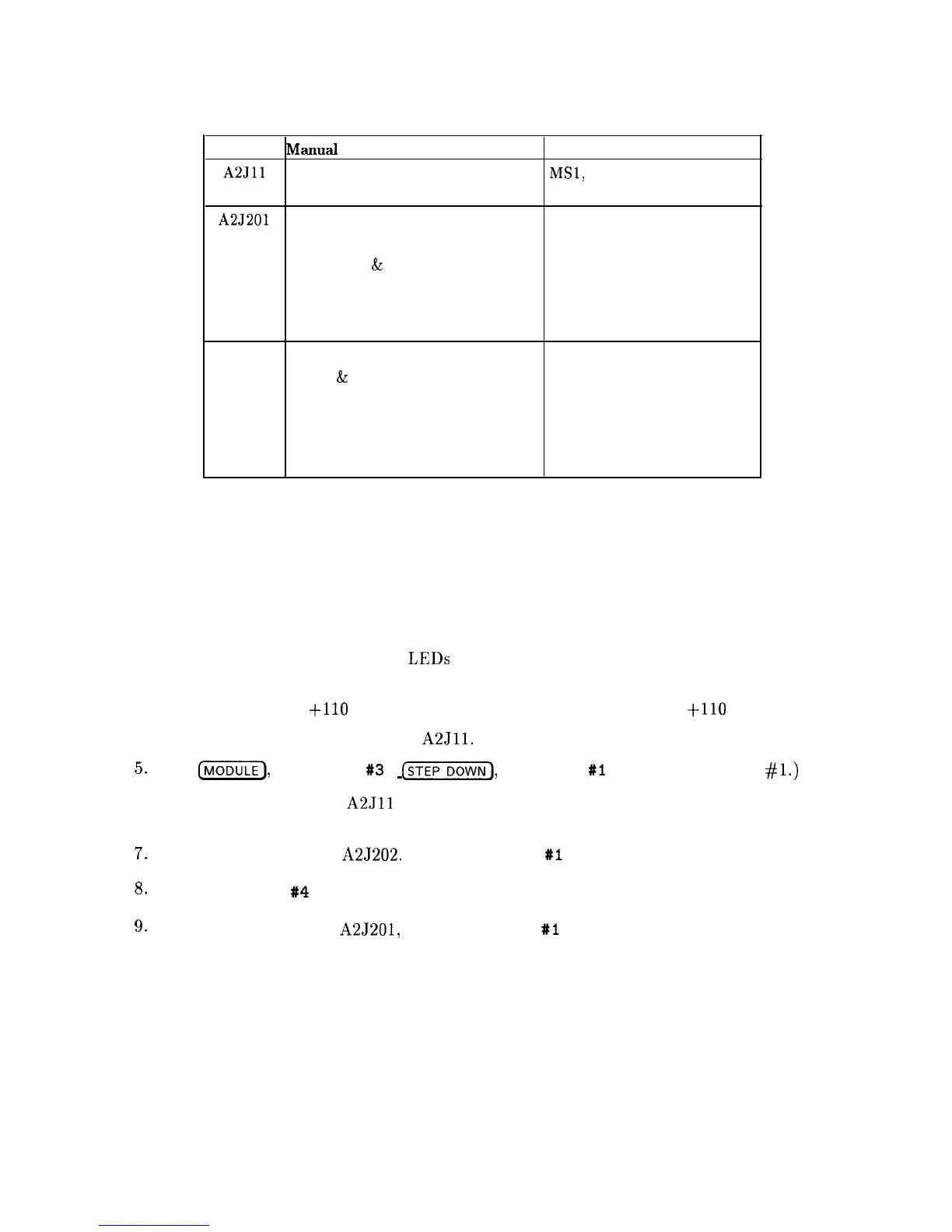
Table 9-1. TAM Tests Versus Test Connectors
Connector
Manual
Probe Troubleshooting Test Measured Signal Lines
A2Jll
ADC/MUX Test
MSl,
MS3 through MS6, MS8
DAC Test
MS2, MS7, OS1
A2J201 10 Volt Reference Test
MS4
Switch Drive Test
MS8
Buffered X
&
Y DAC Outputs
MS2, MS7
X Line Gen Test
MS6
Y Line Gen Test
MS1
Intensity Offset Output
MS3
A2J202 Revision
MS1
X, Y,
&
Z Output Offset
MS3, MS4, MS7
X Output Amplifier
MS3
Y Output Amplifier
MS7
Blanking Test
MS8
Focus DAC Test
MS2
Blank Display
.
Use the following procedure if the instrument’s display is blank. This procedure substitutes an
HP-IB printer for the display.
1. Connect the printer to the HP 8560A and set the printer’s address to the value required
by the TAM. This is usually 1.
2. All of the power-supply indicator
LEDs along the edge of the A2 Controller assembly
should be lit.
3. The rear-panel CRT
+llO
VDC ON indicator might not be lit, even if
+llO
V is present.
4. Connect the TAM’s probe cable to
A2Jll.
5.
Press
(-1,
SOFT KEY 83 ,
[DOWN),
SOFT KEY
#I
. (The top soft key is
#l.)
6. The yellow LED next to
A2Jll
should blink approximately ten times. If the LED fails to
blink correctly, troubleshoot the digital section of the A2 Controller assembly.
7.
Move the probe cable to A2J202. Press SOFT KEY
#I
and wait five seconds.
8.
Press SOFT KEY
#4
. The results should be sent to the printer.
9.
Move the probe cable to A2J201, press SOFT KEY Xl and wait five seconds.
9-2 Controller Section