A9 Input Attenuator
1. Perform the Input Attenuator Accuracy test in Chapter 3 of the Installation and
Verification Manual.
2. If there is a step-to-step error of approximately 10 dB or more, continue with step 3.
3. On the HP 8560A press
[n),
and
ATTEN
AUTO
MAN
until
HAN
is underlined.
4. Step the RF
ATTEN
from 0 dB to 70 dB. A “click” should be heard at each step. The
absence of a click indicates faulty attenuator drive circuitry.
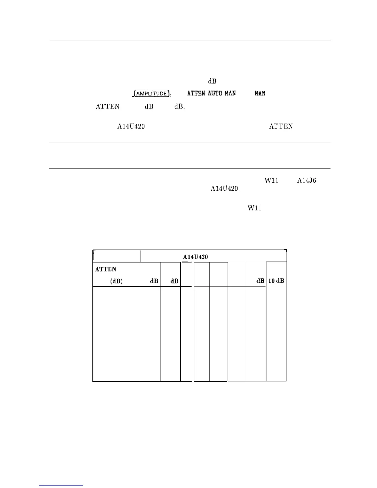
5. Monitor the pins of A14U420 with a logic probe or DVM while setting
ATTEN
to the
values listed in Table 11-3.
Note
The logic levels listed in Table 11-3 show the default AC usage (Pin 5 low, Pin
6 high). DC usage (Pin 5 high, Pin 6 low) is not shown.
6. If one or more logic levels listed in Table 11-3 is incorrect, disconnect
Wll
from A14J6 and
repeat step 4 checking only pins 3, 5, 11, and 13 of A14U420. Pins 4, 6, 10, and 12 should
all read low TTL levels.
7. If one or more logic levels listed in Table 11-3 is incorrect with
Wll
disconnected,
troubleshoot the Al4 Frequency Control assembly.
8. If all logic levels are correct, the A9 Input Attenuator is probably defective.
Table 1 l-3. Attenuator Pin Values
A14U420
Pin Number
ATTEN
Setting
(dB)
0
high
10
high
20
low
30
low
40
high
50
high
60
low
70
low
3
4
20 dB 20 dB
low
low
high
high
low
low
high
high
-
5
DC
-
low
low
low
low
low
low
low
low
-
6
10
AC 40dB
high low
high low
high low
high low
high high
high high
high high
high high
11 12
40dB 10
dB
high
low
high high
high
low
high high
low
low
low
high
low low
low
high
13
10
dB
high
low
high
low
high
low
high
low
RF Section 11-7