Procedure 14. W3 Line Switch Cable
18. Fold out the Al4 and Al5 assemblies as described in Procedure 9, “Al4 and Al5
Assemblies Removal,” steps 3 and 4.
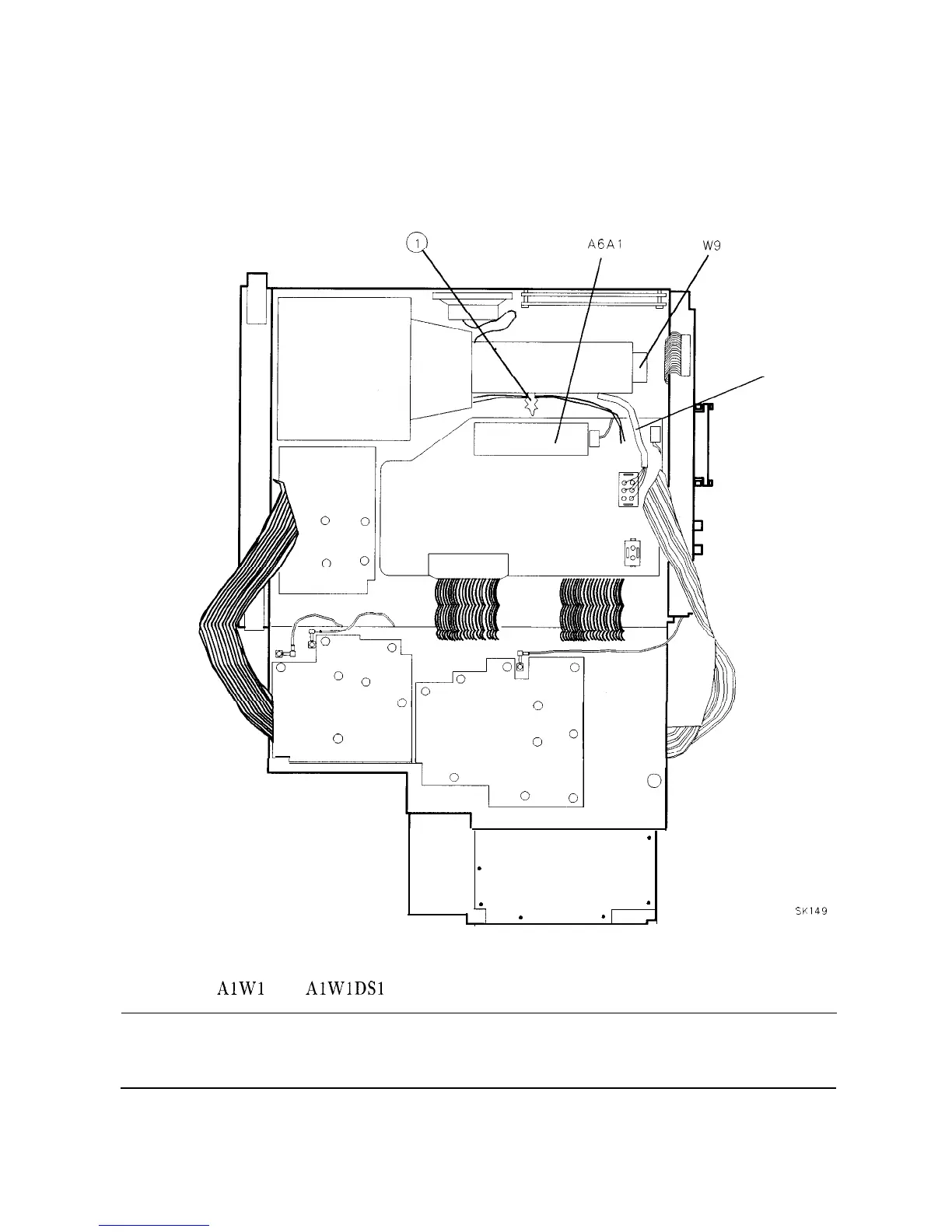
19. Remove the screw (1)
securing W3, the line switch assembly, to the front frame. The
screw is captive. See Figure 3-25.
A6Al
w9
0 0
0
0
0
0
0
-
0
0 0
.
.
.
.
11
.
.
I-
Figure 3-24. W3 Dress and Connection to A6 Power Supply
20. Remove
AlWl
and
AlWlDSl
from the line-switch assembly. Let each hang freely.
Note
If contact removal tool, HP part number 8710-1791, is available, complete
assembly removal by performing “Removal” steps 21 and 22. If not, skip to
“Removal” step 23.
w3
SK
149
Assembly Replacement 3-45