2. Set the HP 8560A to the following settings:
SPAN
. . . . . . . . . . . . . . . . . . . . . . . . . . . . . . . . . . . . . . . . . . . . . . . . . . . . . . . . . . .
OHz
CENTER FREQ
. . . . . . . . . . . . . . . . . . . . . . . . . . . . . . . . . . . . . . . . . . . .
389.5MHz
CF STEP . . . . . . . . . . . . . . . . . . . . . . . . . . . . . . . . . . . . . . . . . . . . . . . . . . . . . 7.5 MHz
3. Use the step keys to tune the CENTER
FREQ
to the values listed in Table 10-l.
4. As the sampling oscillator frequency is increased, the DVM reading should also increase.
The voltage remains at approximately
+5.5
Vdc. If the tune voltage is correct, but the
ADC measures the voltage and determines it to be out of specification, troubleshoot the
A3 assembly’s ADC MUX.
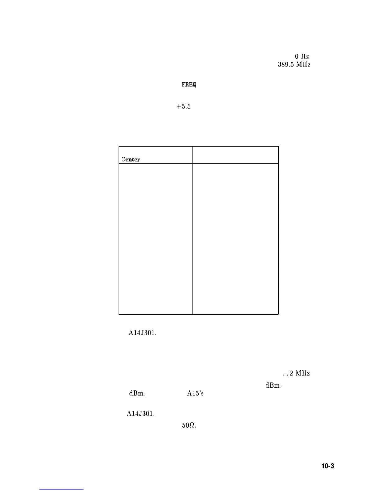
Table 10-l. Center Frequency Tuning Values
HP 8560A
sampling
Zenter Frequency (MHz) Oscillator’s Frequency (MHz)
389.5
280.0
427.0
282.5
449.5
284.0
464.5
285.0
479.5
286.0
502.0
287.5
509.5
288.0
539.5
290.0
569.5
292.0
577.0
292.5
599.5 294.0
614.5
295.0
629.5 296.0
652.0 297.5
659.5
298.0
5. Disconnect W37 from A14J301.
6. Connect a test cable from W37 to the input of another spectrum analyzer. Tune the other
spectrum analyzer to the following settings:
Center Frequency
. . . . . . . . . . . . . . . . . . . . . . . . . . . . . . . . . . . . . . . . . . . . . . . 10 MHz
Span
. . . . . . . . . . . . . . . . . . . . . . . . . . . . . . . . . . . . . . . . . . . . . . . . . . . . . . . . .
..2MHz
7. The amplitude of the 10 MHz reference signal should measure >-1
dBm.
If the signal
does not measure >-1
dBm,
troubleshoot
A15’s
10 MHz Distribution and A21 OCXO
(if Option 003 is present).
8. Reconnect W37 from
A14J301.
9. Connect the CAL OUTPUT to INPUT
50R.
Synthesizer Section
10-3