17. Signal ID Oscillator Adjustment
17. Signal ID Oscillator Adjustment
Assembly Adjusted
Al5 RF Assembly
Related Performance Test
There is no related performance test for this adjustment procedure.
Description
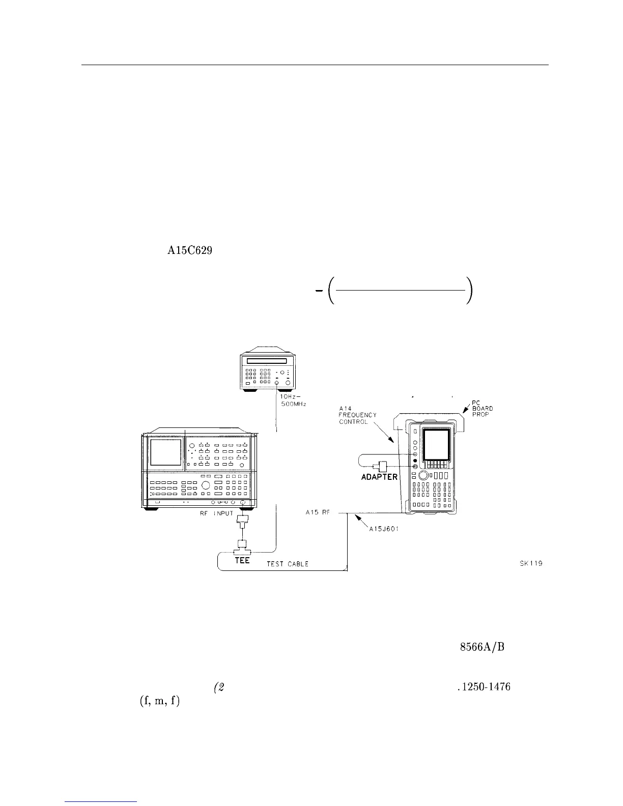
The frequency range of the 298 MHz Signal ID Oscillator is determined by counting the
10.7 MHz IF as A15C629 is rotated through its range of adjustment. The Signal ID Oscillator
is then set to the frequency determined by the following equation:
Oscillator frequency = 298 MHz
-
Oscillator frequency range
4
>
FREQUENCY
COUNTER
SIGNAL
ANALYZER
ADAPTER
Y
1
Al5
RF
+
TEE
TEST
CABLE
Al4
SPECTRUM
ANALYZER
FREOUENCYFREOUENCY
\
\
A15J601
,’
PC
BOARD
I
PROP
Figure 2-20. Signal ID Oscillator Adjustment Setup
Equipment
Microwave Frequency Counter
. . . . . . . . . . . . . . . . . . . . . . . . . . . . . . . . . . . . . HP 5343A
Spectrum Analyzer . . . . . . . . . . . . . . . . . . . . . . . . . . . . . . . . . . . . . . . . . . . . . HP
8566A/B
Adapters
Type N (m) to BNC (f) (2 required)
. . . . . . . . . . . . . . . . . . . . . . . . . . . . . . . . .1250-1476
BNC Tee
(f,m,f)
. . . . . . . . . . . . . . . . . . . . . . . . . . . . . . . . . . . . . . . . . . . . . . ...1250-0781
SK1
19
Adjustment Procedures 2-63