Procedure 1. Analyzer Cover
Procedure 1. Analyzer Cover
Removal/Replacement
1. Disconnect the line-power cord, and place the analyzer on its front panel.
2. Loosen (but do not remove) the four rear-bumper screws, using a 4 mm hex wrench. Pull
the cover assembly off towards the rear of the instrument.
Caution
When replacing the analyzer’s cover, use caution to avoid damaging any
cables.
3.
4.
When installing the cover assembly, be sure to locate the cover’s air vent holes on the
bottom side of the analyzer. Attach with the four screws loosened in step 2, and tighten
the four screws gradually to ensure that the cover is seated in the front-frame gasket
groove.
Torque each screw to 40 to 50 inch-pounds to ensure proper EM1 gasket compression.
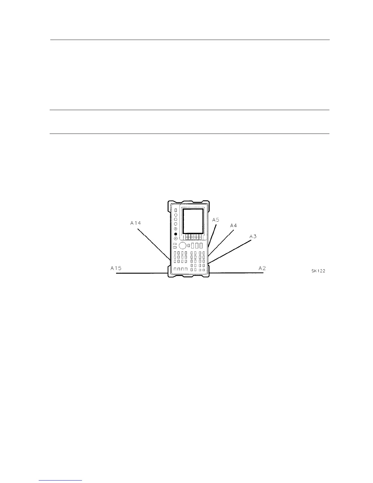
SK122
Figure 3-1. Hinged Assemblies
Assembly Replacement 3-3