.-mm-----
10 7 MHz
I
CAL OSC
i
+lV
DC
J3
[_:
I
I
I
LINEAR
I
I
I
L
---------I
IF ADJ OFF
i
W54
DISCONNECTED
]+I-
p-
I
w54
LOG
34
,‘-,
J
I
u
(RED)
*
P
I
WITH COUNTER ON
i
BURSTS OF 5.35 MHz
I
I
APPROX 10
mSEC
5
“P-P
I
w53
A
i2
IJ5
(-‘,
I
Jb
!
l&
(BROWN)
w55
LAM/FM
J6
f-t
-
DEMOD
I
!+A!
(WHITE/
)
I
BLUE)
I
, A4 LOG AMP/CAL OSC ASSEMBLY
;
b-------------------
w27
A
~5
OdBm
10.7 MHz
F ADJ OFF
(ORANGE)
/
SK171
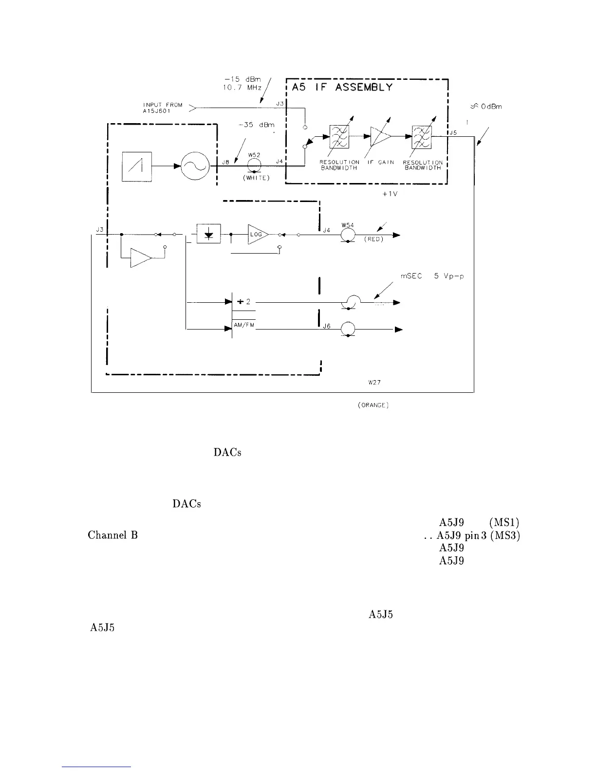
Figure 8-2. IF Section Troubleshooting with TAM
Both the digital control and DACs are multiplexed onto test point “channels” through
resistive networks. One DAC from each of the quad-DAC packages feeds into a network.
The TAM varies each DAC individually to isolate which ones failed. Similarly, 10
digitally-controlled lines feed into a network and are monitored by the TAM. The channels
used to monitor the DACs are listed below:
Channel A
. . . . . . . . . . . . . . . . . . . . . . . . . . . . . . . . . . . . . . . . . . . . . . . . . . . . . . A5J9 pin 1
(MSl)
ChannelB
. . . . . . . . . . . . . . . . . . . . . . . . . . . . . . . . . . . . . . . . . . . . . . . . . . . . .
..A5Jgpin
3(MS3)
Channel C
. . . . . . . . . . . . . . . . . . . . . . . . . . . . . . . . . . . . . . . . . . . . . . . . . . . . . . A5J9 pin 4 (MS4)
Channel D
. . . . . . . . . . . . . . . . . . . . . . . . . . . . . . . . . . . . . . . . . . . . . . . . . . . . . . A5J9 pin 2 (MS2)
1. On the spectrum analyzer, enter the TAM Cal Osc Troubleshooting Mode by selecting
diagnose then Cal Osc Troubleshooting Mode.
2. On the spectrum analyzer, disconnect W27 (
coax 3) from A5J5 and monitor the output of
A5J5 with a second spectrum analyzer.
IF Section 8-7