13.
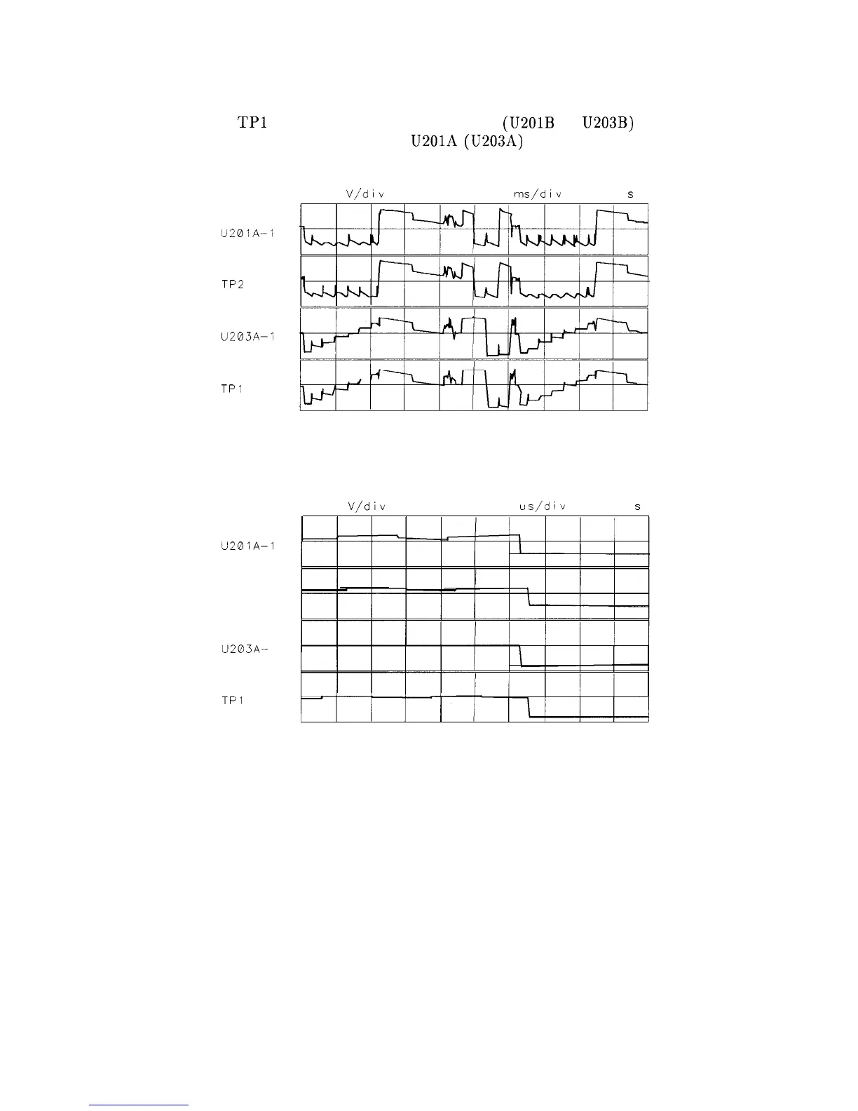
Figure 9-8 illustrates the waveforms of properly working line generators. Whenever there
is a pulse on
TPl
or TP2, the appropriate integrator (U201B or U203B) generates a ramp
(the output vector) which feeds back to U201A (U203A) and shows on its output.
5.0
V/div
0.00 v 1.00
ms/div
0 000
s
U201A-1
TP2
U203A-1
TPI
SK195
Figure 9-6. Distorted X/Y Line Generator Waveforms
5.0
V/div
0.00 v 20 0
us/div
0.000
s
U201A-1
TP2
U203A-
1
TPl
SK196
Figure 9-7. Expanded X/Y Line Generator Waveforms
Controller Section 9-9