Procedure 10. Al7 CRT Driver
Procedure 10. Al7 CRT Driver
Removal
1. Remove the analyzer’s cover assembly and fold out the A2, A3, A4, and A5 assemblies as
described in Procedure 5, “A2, A3, A4, and A5 Assemblies Removal,” steps 3 through 6.
2. Place the analyzer top-side-up on the work bench with A2, A3, A4, and A5 folded out to
the right.
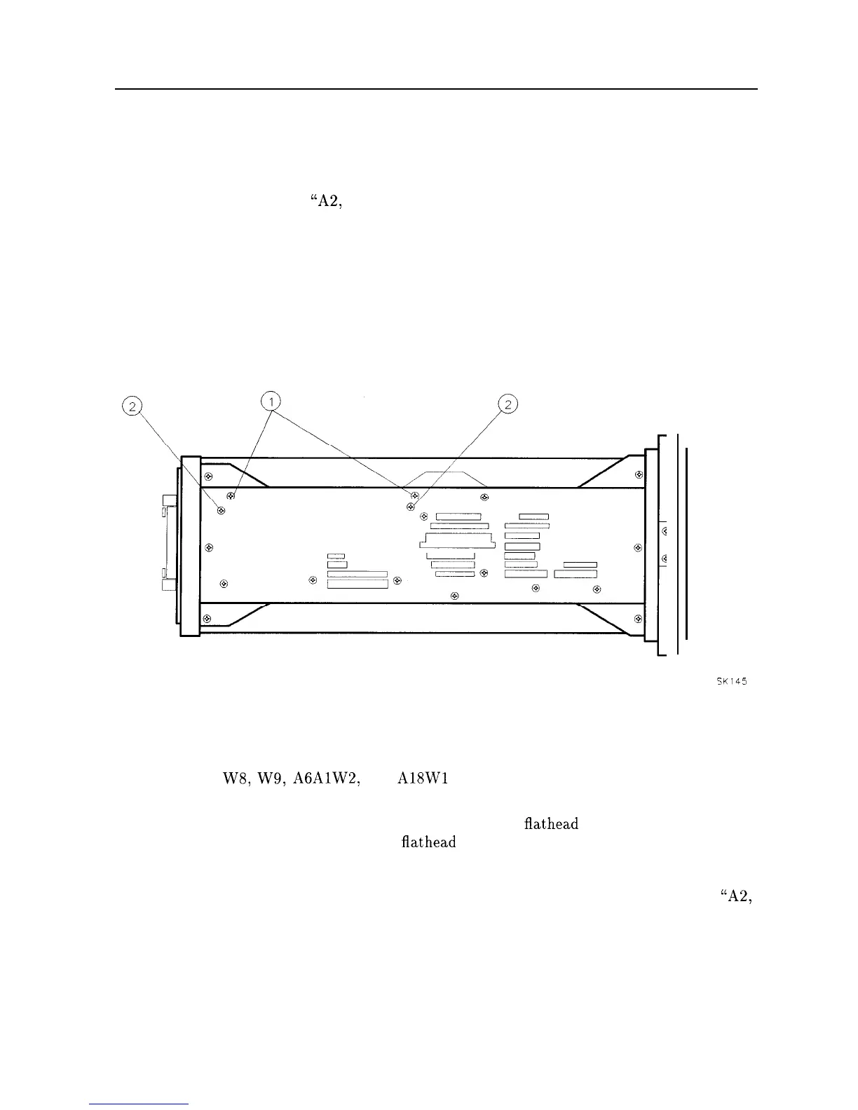
3. Remove two screws (1) securing the two board-mounting posts to the left-side frame, and
remove the posts. See Figure 3-21.
4. Remove two screws (2) securing Al7 assembly to the left-side frame.
5. Pull the Al7 Assembly out of the analyzer.
SK145
Figure 3-21. Al7 Mounting Screws
Replacement
1. Connect W7, W8, W9,
A6AlW2,
and
A18Wl
to the Al7 CRT Driver Assembly. Place the
assembly into the center-deck mounting slot next to the CRT assembly.
2. Secure the Al7 assembly to the left side frame using two
flathead
screws. Attach the board
mounts to the left side frame using two
flathead
screws. See Figure 3-21.
3. Place the analyzer on its right side frame.
4. Fold the A2, A3, A4, and A5 assemblies into the analyzer as described in Procedure 5,
“A2,
A3, A4, and A5 Assemblies.”
Secure the analyzer’s cover assembly.
Assembly Replacement 3-37