14. External Mixer Bias Adjustment
14. External Mixer Bias Adjustment
Assembly Adjusted
Al5 RF Assembly
Related Performance Test
There is no related performance test for this adjustment procedure.
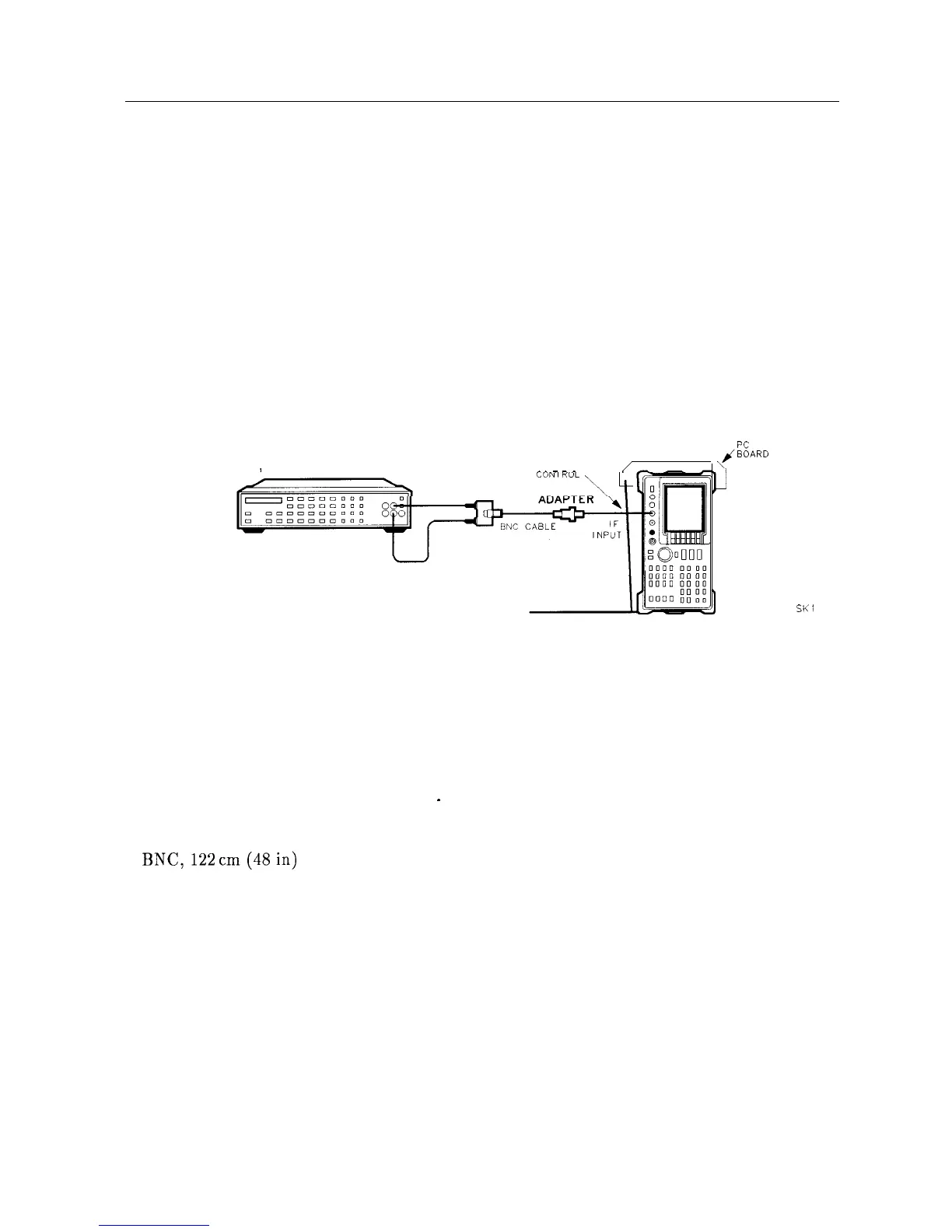
Description
A voltmeter is connected to the HP 8560A IF INPUT with the external mixer bias set to off.
The bias is adjusted for a 0 Vdc output.
Al4
SPECTRUM
ANALYZER
DIGITAL VOLTMETER
FREQUENCY
/
^ ^
-
-
^
ADAPTER
Al5 RF
kRD
PROP
SK1
16
Figure 2-17. External Mixer Bias Adjustment Setup
Equipment
DVM . . . . . . . . . . . . . . . . . . . . . . . . . . . . . . . . . . . . . . . . . . . . . . . . . . . . . . . . . . HP 3456A
Adapters
Type BNC (f) to SMA (m)
. . . . . . . . . . . . . . . . . . . . . . . . . . . . . . . . . . . . . . . . 1250-1200
Type BNC (f) to dual banana plug
. .
_
. . . . . . . . . . . . . . . . . . . . . . . . . . . . . . 1251-2816
Cables
BNC,122
cm(48in)
. . . . . . . . . . . . . . . . . . . . . . . . . . . . . . . . . . . . . . . . . . . . HP 10503A
Procedure
1. Set the HP 8560A (LINE) switch off and disconnect the ac power cord. Remove the analyzer
cover and connect the equipment as illustrated in Figure 2-17. Reconnect the power cord
and set the (LINE) switch on.
2. Set the HP 3456A controls as follows:
FUNCTION
. . . . . . . . . . . . . . . . . . . . . . . . . . . . . . . . . . . . . . . . . . . . . . . . DCVOLTS
RANGE...........................................................O.lV
RESOLUTION
. . . . . . . . . . . . . . . . . . . . . . . . . . . . . . . . . . . . . . . . . . . . . . . . ..lOOmV
Adjustment Procedures 2-55