Procedure 5. A2,
A3,
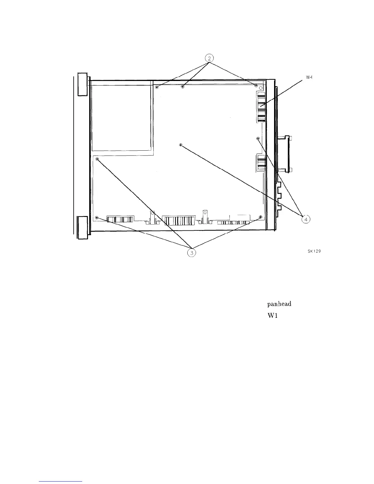
A4, and A5 Assemblies
Figure 3-7. A2, A3, A4, and A5 Assembly Removal
SK129
Replacement
1. Place the analyzer top-side-up on the work bench.
2. Attach the assembly being installed to the two chassis hinges with two
panhead
screws.
3. Leave the assembly in the folded-out position and attach ribbon cables
Wl
and W2.
4. Attach all coaxial cables to the assembly, as illustrated in Figure 3-9.
5. Locate the cable clip on the inside of the right-side frame. Make sure that the coaxial
cables are routed properly on the clip as illustrated in Figure 3-9.
6. Lay the A2, A3, A4, and A5 assemblies flat against each other in the folded-out position.
Make sure that no cables become pinched between any two assemblies.
3-14 Assembly Replacement