Procedure 5.
A2, A3, A4, and A5 Assemblies
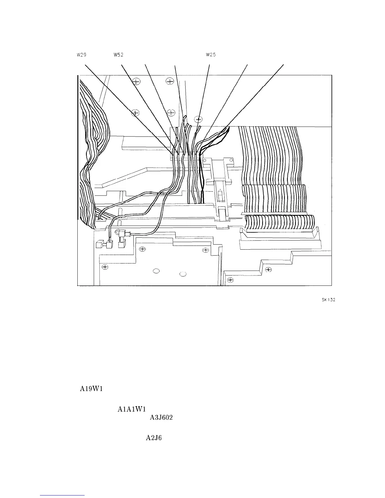
w29
W52
W27 W23
W25
w22
COAX 7 COAX 9 COAX 3 COAX 93 COAX 4 COAX 0 W6
SK132
Figure 3-9. Coaxial Cable Clip
7. Check to ensure that no cables will become pinched under the hinges when folding up the
A4 and A5 assemblies.
8. Fold the A4 and A5 assemblies together as a unit into the analyzer. Use caution to avoid
damaging any cable assemblies. The standoffs on the A5 assembly must fit into the cups
on the A6 power supply top shield.
9. Fold the A2 and A3 assemblies together as a unit into the analyzer. Be sure to fold HP-IB
cable
A19Wl
between the A3 and A4 assemblies, using the two sets of hook and loop
(velcro) fasteners.
10. Fold ribbon cable
AlAlWl
between A3 and A4 assemblies. Take care to dress the
protective tubing as close to A3J602 connector as possible, so that the tubing does not
fold with the cable. See Figure 3-10.
11. Attach ribbon cable W4 to A2J6 while folding up the assemblies. See Figure 3-7.
12. Secure the assemblies using the eight screws removed in “Removal” step 3. Place a flat
washer on each screw.
Assembly Replacement 3-17