3.
4.
5.
6.
7.
8.
9.
10.
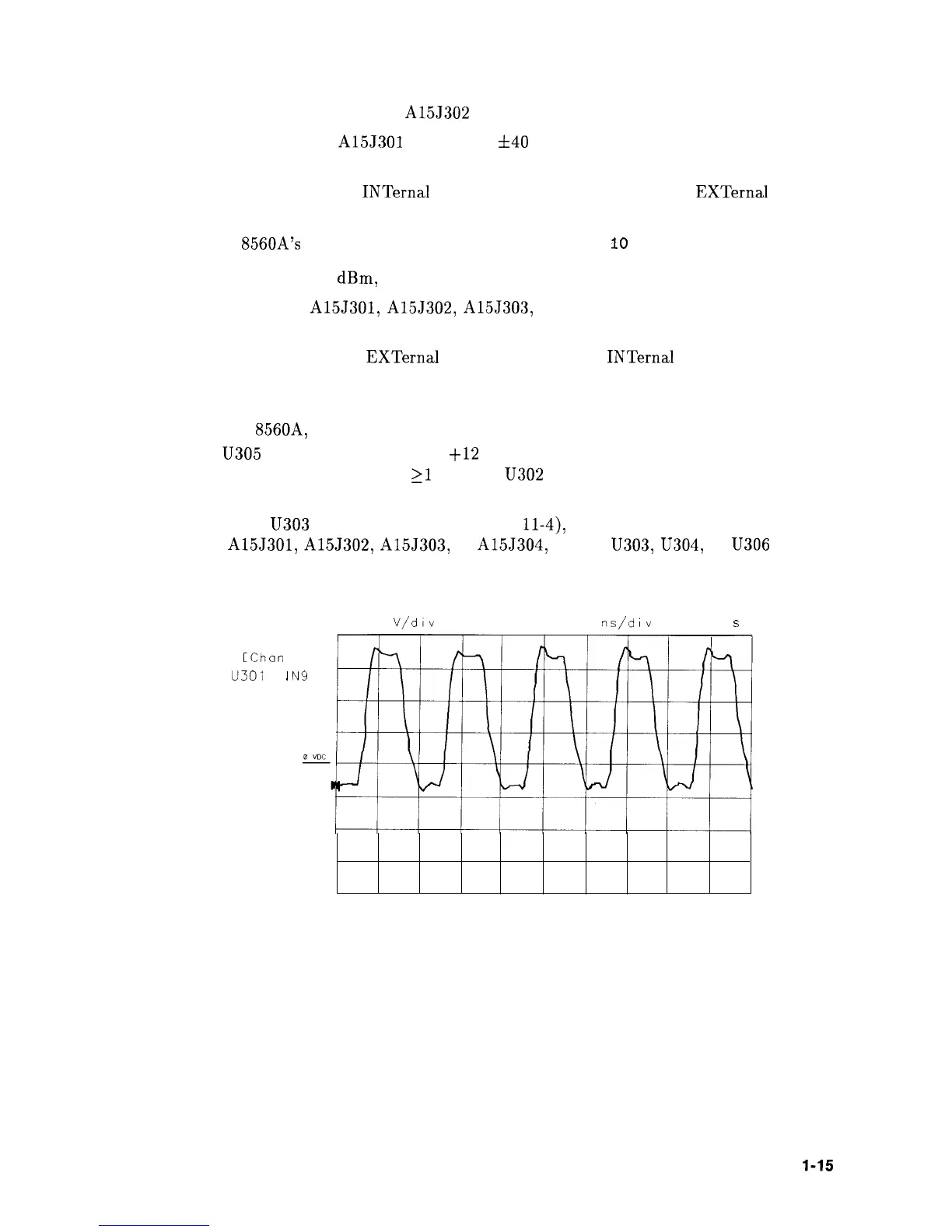
Check for a 3 Vp-p waveform at A15J302 using an oscilloscope (see Figure 11-3).
Check that the signal at A15J301 is 10 MHz
640
Hz (with TCXO reference) using a
frequency counter. If necessary, perform the appropriate 10 MHz reference adjustment.
If there is no problem with
INTernal
10 MHz reference operation, check
EXTernal
10 MHz
reference operation as follows:
Set the HP
8560A’s
10 MHz reference to external by pressing
10
MHz EXT .
Connect a 10 MHz, -2
dBm,
signal to the rear-panel 10 MHz REF IN/OUT connector.
Check the signals at A15J301, A155302, A15J303, and A15J304 according to the
procedure in steps 2 through 4.
If the signals are correct in
EXTernal
operation, but not in
INTernal
operation, the
problem lies in the TCXO, its voltage reference, the TTL level generator, or the A21
OCXO, if Option 003. Check these sections as follows:
On the HP
8560A, press 10 MHz INT .
Check
U305
pin 3 for approximately
+12
Vdc.
Check for a 10 MHz sine wave,
21
Vp-p, at
U302
pin 2 (non-option 003) or J305
(Option 003) using an oscilloscope.
If the signal at
U303
pin 5 is correct (see Figure
ll-4),
but there is a problem with the
signals at A15J301, A15J302, A155303, or A15J304, suspect U303,
U304,
or
U306
in the
10 MHz Distribution Amplifier.
Graph I
1 1
1 00
V/div
0 00 v 50 0
ns/div
0 000
s
1:
[Char-
1 1
u301
P
I
N9
Figure 11-3. 10 MHz Reference at A15J302
RF Section 1 l-15