6. Sampling Oscillator Adjustment
6. Sampling Oscillator Adjustment
Assembly Adjusted
Al5 RF Assembly
Related Performance Test
There is no related performance test for this adjustment procedure.
Description
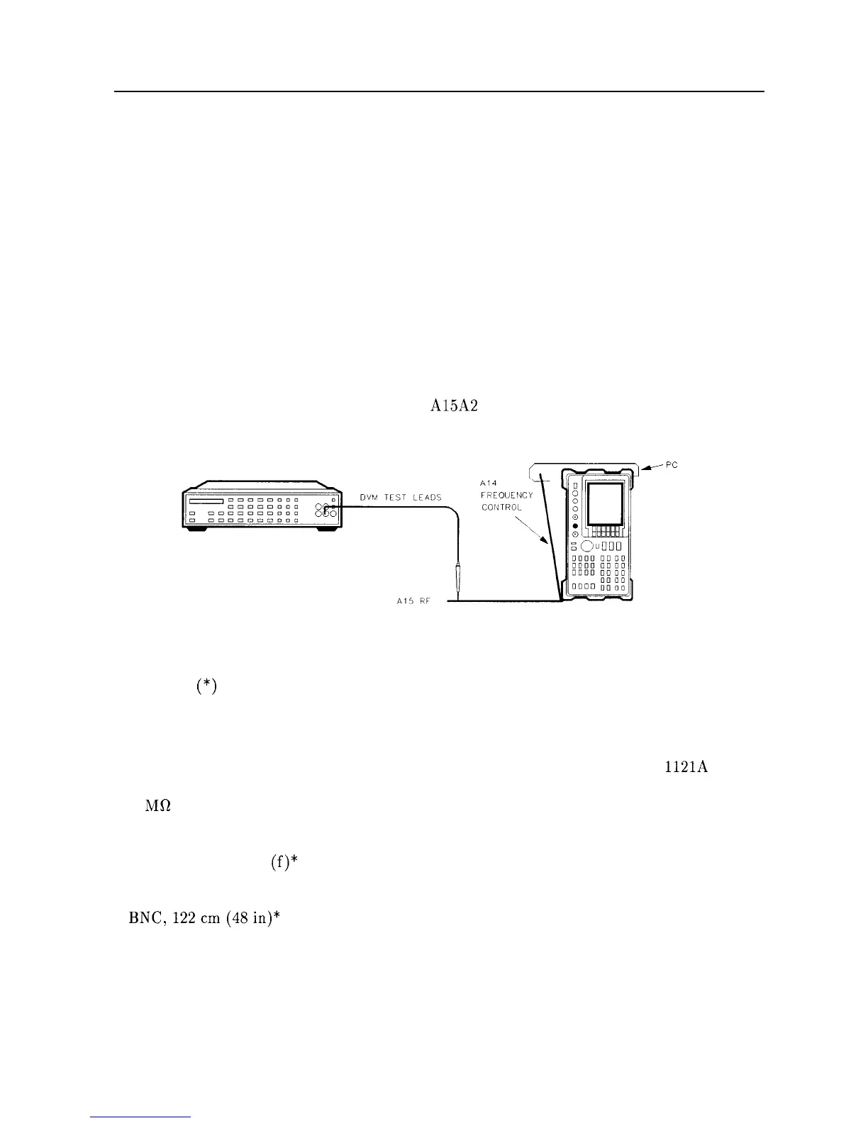
The phase detector bias is adjusted for 1.8 Vdc. The sampling oscillator tank circuit is
adjusted for a tuning voltage of 0.9 Vdc when the oscillator is set to 288 MHz. The voltage
monitored is actually the tuning voltage divided by 4.05. A coarse-tune procedure is also
included, but should only be necessary when the coaxial resonator is replaced. The power and
match of the sampling oscillator signal to the A15A2 Sampler are also adjusted.
DIGITAL VOLTMETER
SPECTRUM ANALYZER
w
PC
BOARD
PROP
Figure 2-8. Sampler Adjustment Setup
Equipment
An asterisk (*) indicates equipment used only for the coarse-tune procedure.
Digital Voltmeter
................................................
HP 3456A
DVM Test Leads
...............................................
HP 34118A
Frequency Counter*
.............................................
HP 5343A
Active Probe*
..................................................
HP
1121A
Power Supply*
..................................................
HP 6114A
1 MR Resistor*
..................................................
0757-0080
Adapters
Type BNC (f) to BNC
(f)’
. . . . . . . . . . . . . . . . . . . . . . . . . . . . . . . . . . . . . . . . 1250-0059
Cables
BNC,122cm(48in)*
. . . . . . . . . . . . . . . . . . . . . . . . . . . . . . . . . . . . . . . . . . HP 10503A
SK17
Adjustment Procedures 2-33