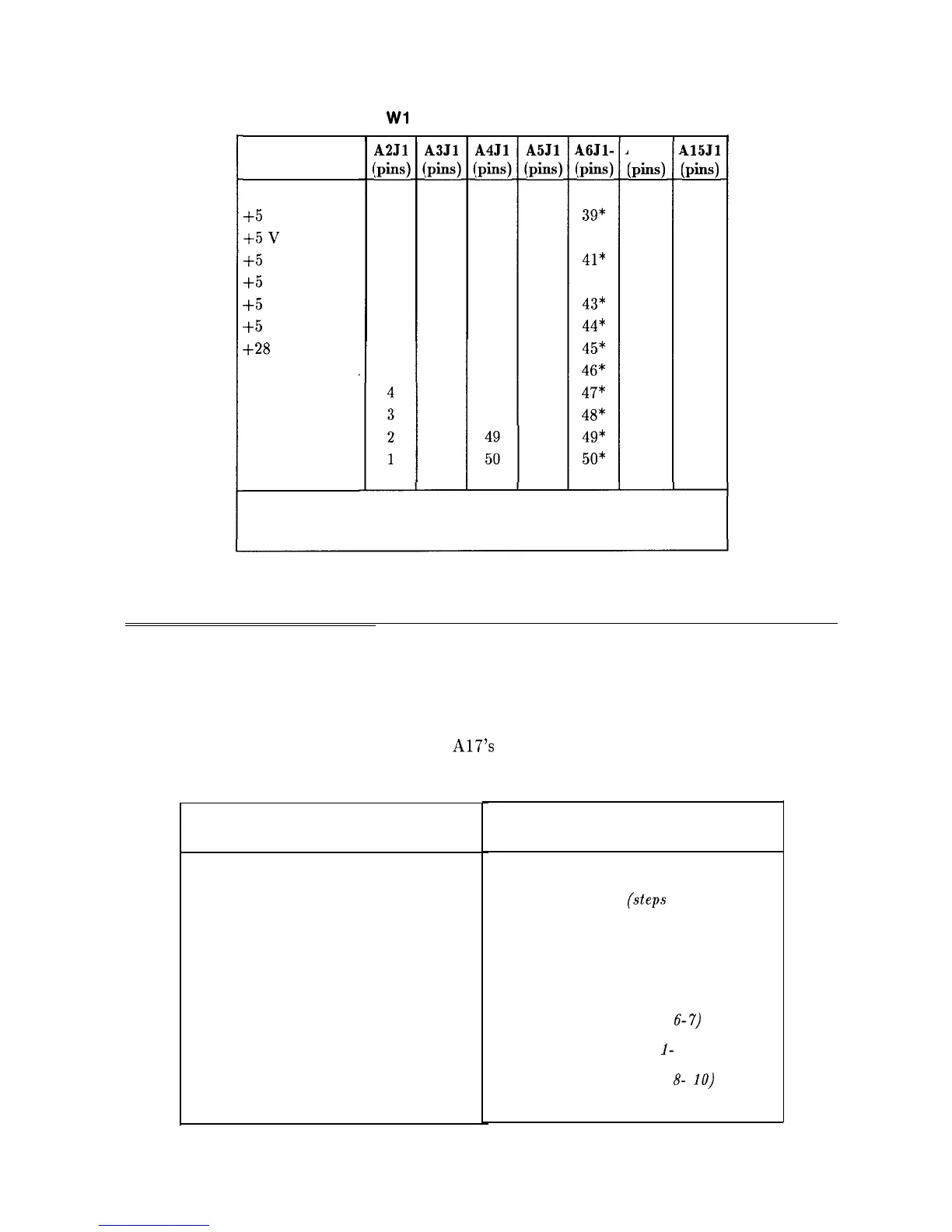
Table 12-1.
Wl
Power-Cable Connections (2 of 2)
Signal
$5
V
$5
v
$5
V
+5
V
+5
V
+5
V
+28
V
LINE TRIGGER
+15 V
+15 V
-15 V
-15 V
A2Jl
:pins)
12
11
10
9
8
7
6
A3Jl
:pins)
39
40
41
42
43
44
45
46
47
48
49
50
A4Jl
:pins)
* Indicates signal source connectors.
A5Jl
:pins)
46Jl-
:pins)
39*
40*
41*
42*
43*
44*
45*
46*
47*
48*
49*
50*
414J1
(Pins)
415Jl
(Pins)
Table 12-2. Automatic Fault Isolation References
Suspected Circuit Indicated
Manual Procedure to Perform
by Automatic Fault Isolation
Check A2 Controller
Blanking Signal
Check All Power Supply Outputs
Dead Power Supply
(steps 1-5)
Check Buck Regulator
Dead Power Supply
(steps 22-23)
Check Buck Regulator Control Circuitry
Dead Power Supply
(steps 11-21)
Check High-Voltage Supplies
High Voltage Supplies
Check Input Rectifier
Dead Power Supply
(steps 6-7)
Check Intensity Adjustments
Intensity Problems
(steps
l-
4)
Check Kick Start/Bias Circuitry
Dead Power Supply
(steps
8-
10)
Check Low-Voltage Supplies
Low Voltage Supplies
Troubleshooting Using the TAM
When using Automatic Fault Isolation, the TAM indicates suspected circuits that need to be
manually checked. Use Table 12-1 to locate the manual procedure.
Table 12-2 lists assembly test connectors associated with each Manual Probe Troubleshooting
test. Figure 12-2 illustrates the location of
A17’s
test connectors.
12-4 Display/Power Supply Section