3. If A14J17 pin 1 does not appear to be correct, verify that the sweep ramp is reaching the
Main/FM/VCO
Sweep
Switch as follows:
Change the oscilloscope’s amplitude scale to 1.25
V/d’
iv
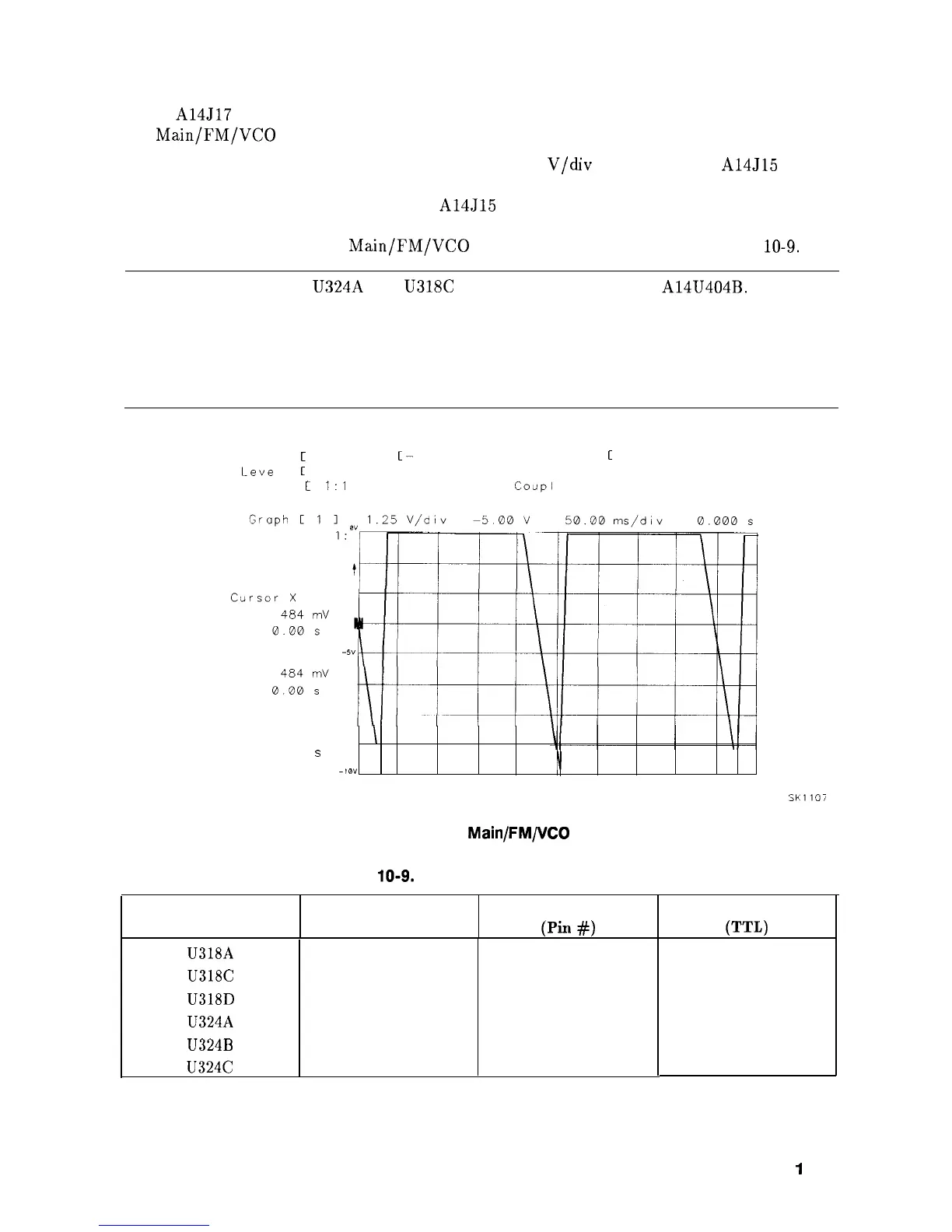
and monitor the A14J15 pin 14.
The waveform should be a 0 V to -10 V sweep of 50 ms duration. See Figure 10-7.
Check for a 0 V to -10 V ramp at A14J15 pin 13. Refer to function block H of Al4
Frequency Control Schematic (sheet 2 of 5).
Check that state of the
Main/FM/VCO
Sweep Switches as indicated in Table
10-9.
Note
Switches U324A and U318C can change the polarity of A14U404B. This
allows the Roller Oscillator to sweep backwards when the YTO is locked to
a lower sideband of a Sampling Oscillator’s comb tooth. The YTO always
sweeps forward (lower frequency to higher frequency), but the Roller Oscillator
sometimes sweeps backwards (higher frequency to lower frequency). The FREQ
DIAGNOSE menu will indicate a negative Main Roller frequency in this instance.
Source
C
Chon 1
1
C-
Slope
1
Auto Scale
C
Enabled
1
Leve
I
C
Adjust
1
-2.500 v
On Event
0000 1
Probe
C
1:l
1
Coup1
ing Cdc 1 Cl Mnl
X Selected
Cursor 0
+”
Cursor O-X
0.00 v
I
0.00
s
-10”
\
SK1107
Figure 10-7. Input to Main/FM/VCO Sweep Switch
Table
10-9.
Settings of Sweep Switches
U318A
Open
1
U318C
Open
9
U318D
Open
16
U324A
Closed
1
U324B
Closed
8
U324C
Closed
9
High
High
High
High
High
High
Switch
Switch State Switch Control Line
(Pin
#I
Control Line State
P-L)
Synthesizer Section
1
O-1 9