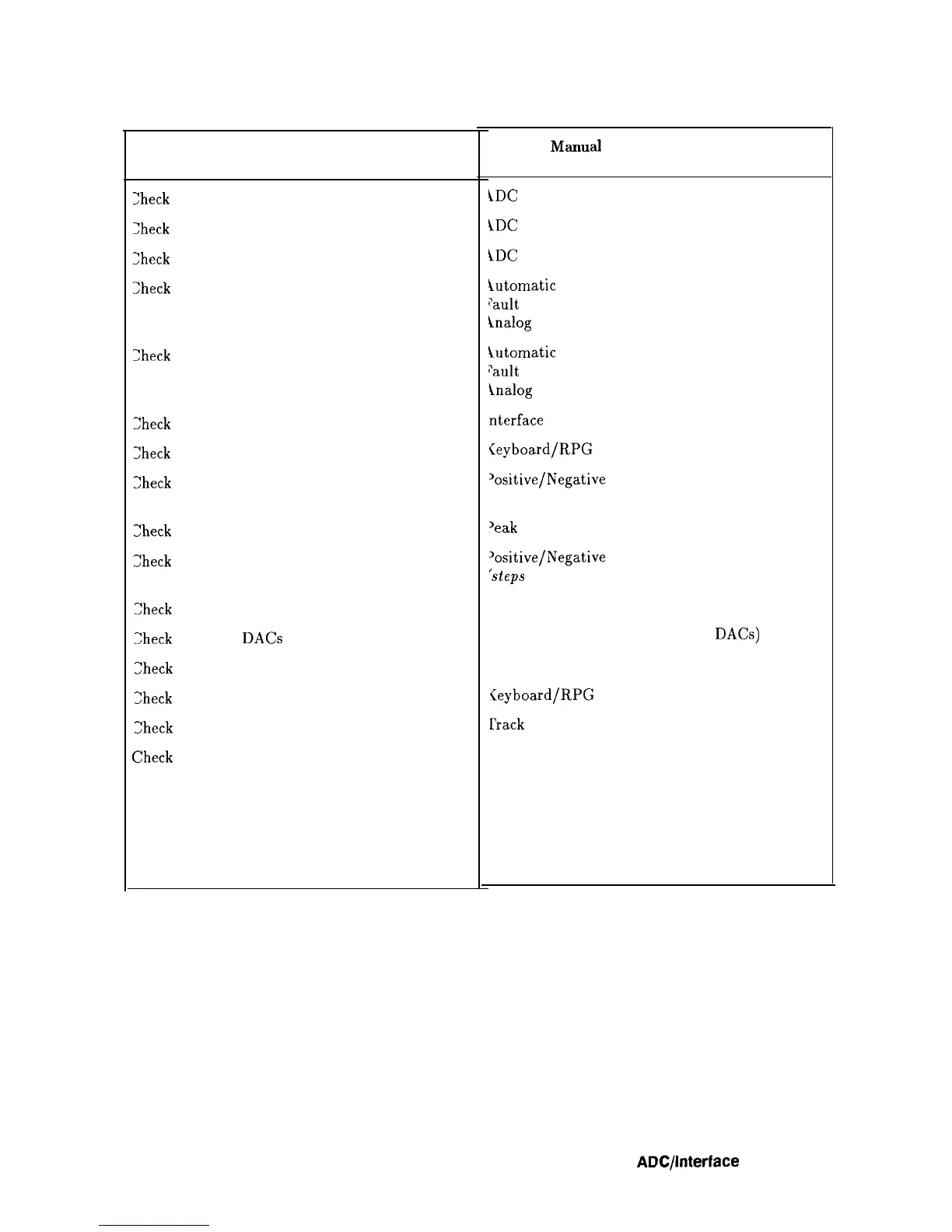
Table 7-2. Automatic Fault Isolation References
Suspected Circuit Indicated
by Automatic Fault Isolation
3heck
ADC ASM
Check
ADC MUX
2heck
ADC Start/Stop Control
Check
Analog Bus Drivers
Check
Analog Bus Timing
2heck
Interface Strobe Select
Check
Keyboard Interface
Check
Negative Peak Detector
Check
Peak Detector Reset
Check
Positive Peak Detector
Check
Ramp Counter
Check
RF Gain
DACs
Check
Rosenfell Detector
2heck
RPG Interface
Check
Track and Hold
v’heck
Trigger
Check Variable Gain Amplifier (VGA)
Check Video Filter
Check Video Filter Buffer Amplifier
Check Video MUX
Manual
Procedure to Perform
\DC
ASM
1DC
MUX
‘LDC
Start/Stop Control
iutomatic
pault
Isolation (in this chapter)
inalog Bus Drivers
lutomatic
‘ault
Isolation (in this chapter)
inalog Bus Timing
nterface
Strobe Select
<eyboard/RPG Problems
‘ositive/Negative Peak Detectors
‘steps 3 through 10)
‘eak Detector Reset
‘ositive/Negative Peak Detectors
(steps
3 through 10)
tamp Counter
3and Flatness Control (RF Gain
DACs)
tosenfell Detector
(eyboard/RPG
Problems
Irack
and Hold
Triggering Problems
Variable Gain Amplifier (VGA)
Video Filter
Video Filter Buffer Amplifier
Video MUX
ADCpterface Section 7-5