14-9
Version 1.73 Copyright © 1997 Link Communications Inc. 1/18/97
The default setup for the RLC-Icom is to have connector 1 plugged into the 140..160
Mhz module, connector 2 plugged into the 220 Mhz module and connector 3 plugged
into the 430..440 Mhz module. As an example, the following commands will enter
those settings again:
Command 139 110 D or unkey or <Enter>
Command 139 215 D or unkey or <Enter>
Command 139 320 D or unkey or <Enter>
Second, you must tell each band module what size of offset to use when you select a
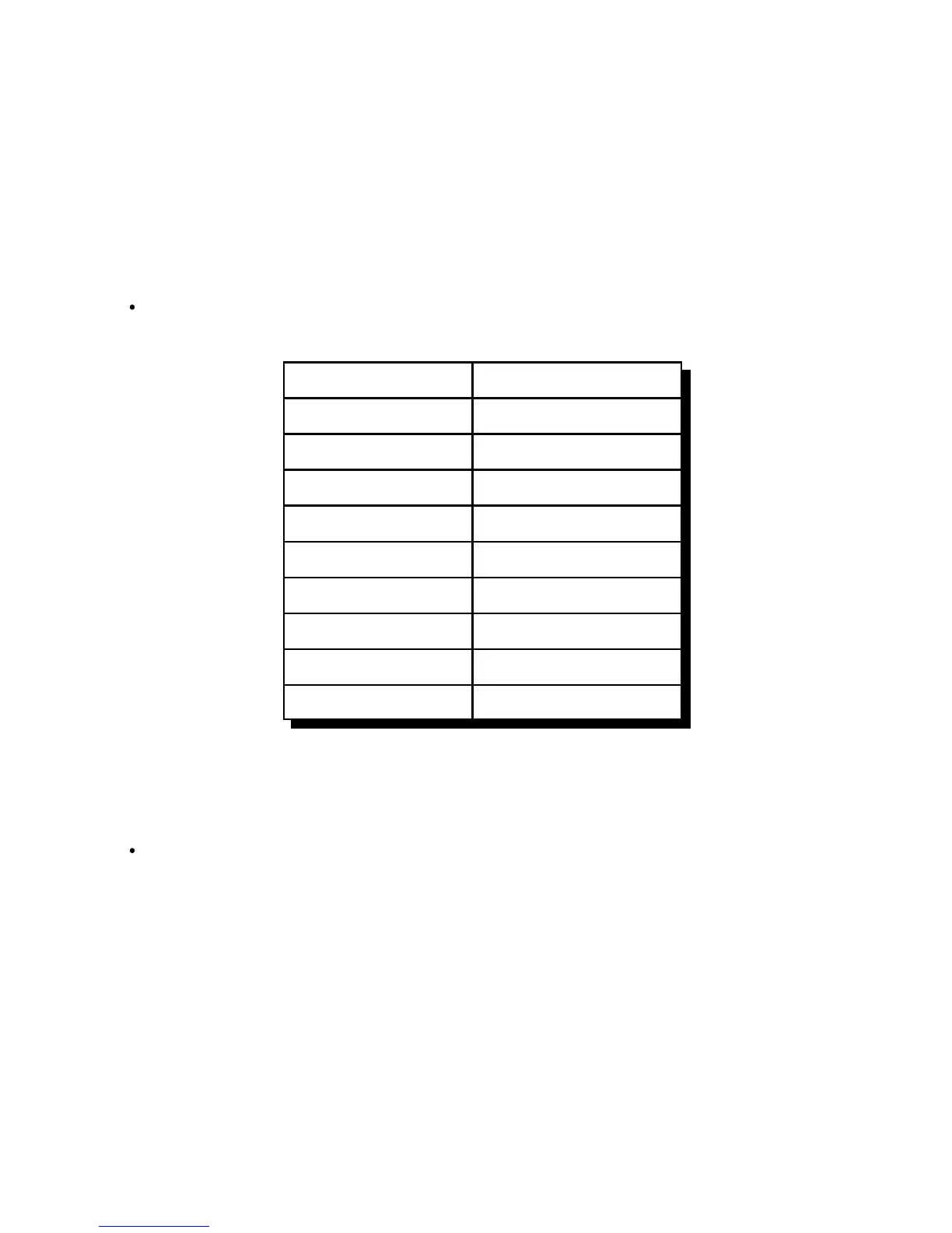
plus or minus offset with Commands 142 or 143. The setup codes follow:
SS (the setup code) Description
30 100 Khz Offset
35 500 Khz Offset
40 600 Khz Offset
45 1 Mhz Offset
50 1.6 Mhz Offset
55 1.7 Mhz Offset
60 5 Mhz Offset
65 12 Mhz Offset
70 20 Mhz Offset
Example:
To select a 100 Khz offset for the 140..160 Mhz module that is plugged into connector
1, enter Command 139 130 D or unkey.
Setup codes 75 and 80 are reserved for special offset memories, which are not yet
supported.
 Loading...