L-INX User Manual 191 LOYTEC
Version 4.0 LOYTEC electronics GmbH
NAT: 135.23.2.1
135.23.2.1
IP Channel 1
Firewall + NAT Router
Internet
IP: 192.168.1.100
Forward ports 1628 and 1629
to IP address 192.168.1.100
IP: 192.168.1.101
IP: 192.168.1.102
IP: 192.168.1.103
TP-1250
High speed
back-bone mode
IP Channel 2
FT-10
FT-10
Configuration
Server for
IP Channel 1
Configuration
Server for
IP Channel 2
192.168.1.1
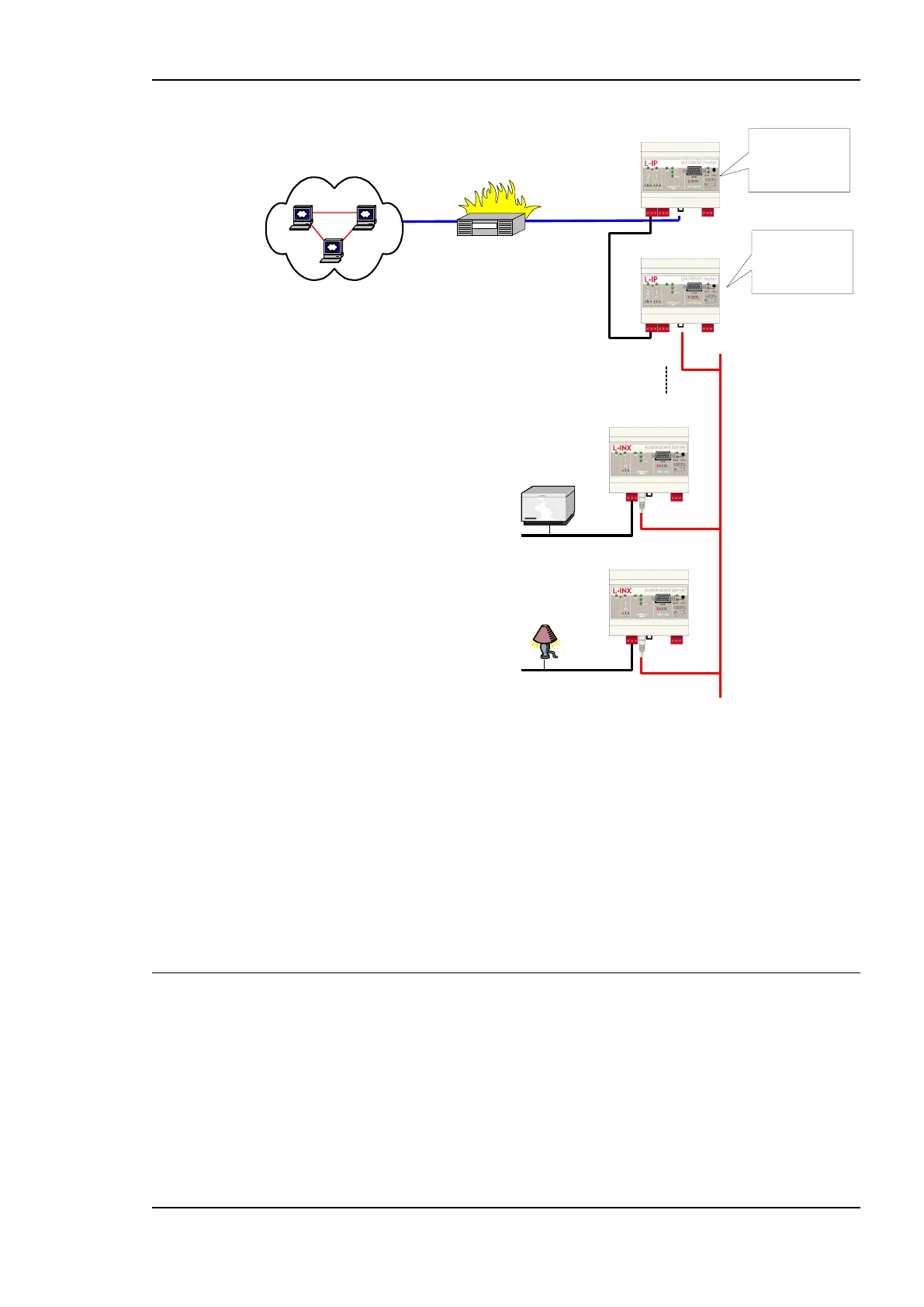
Figure 155: Application that uses multiple L-INX devices behind a NAT router firewall.
The L-INX with IP address 192.168.1.100 is member of IP Channel 1 and can be accessed
through the Internet. The L-INX devices with IP addresses 192.168.101 to 192.168.1.110
form another logical IP Channel 2 that communicates with the devices on the IP Channel 1
over the TP-1250 channel, which is used in high-speed backbone mode for optimum
networking performance. Note that devices on both IP Channels 1 and 2 can of course
connect to the same physical network wiring. Furthermore, both IP Channels 1 and 2 must
have a separate configuration server that manages the L-INX devices on the different
channels. In the example in Figure 155, the L-INX with address 192.168.1.100 acts as the
configuration server for IP Channel 1 and the L-INX with IP address 192.168.1.101 acts as
the configuration server for IP Channel 2.
7.4 Multi-Cast Configuration
IP multi-casting is a feature of the IP protocol that allows one packet to be delivered to a
group of IP hosts. To receive such multi-cast packets, each IP host must be member of a
multi-cast group. This group is identified by a multi-cast address (e.g., 225.0.0.37) and a
UDP port number.
The L-INX supports both unicast and multi-cast delivery of CEA-852 data packets. Using
multi-cast is recommended when using the router in the Smart Switch Mode. For those
devices, configure a multi-cast address in the IP configuration menu. Please contact your
system administrator to obtain a valid multi-cast address for your network. Note, that all