L-INX User Manual 48 LOYTEC
Version 4.0 LOYTEC electronics GmbH
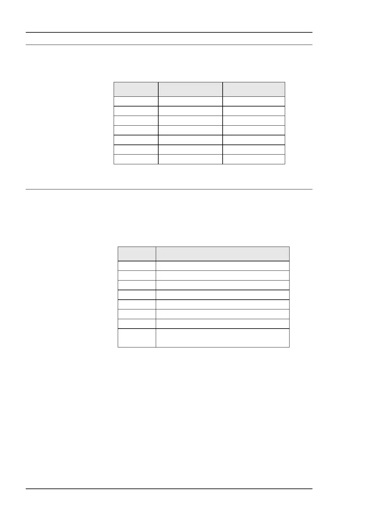
3.7 DIP Switch Settings
The DIP switch assignment for the device is shown in Table 5. Please leave all switches at
default state. Note, that the L-INX models 12X, 15X, 22X do not have DIP switches.
Table 5: DIP Switch Settings.
3.8 Terminal Layout and Power Supply
3.8.1 LINX-10X/11X
The LINX-10X/11X provides pluggable screw terminals to connect to the network as well
as to the power supply. The screw terminals can be used for wires of a maximum thickness
of 2.5 mm
2
/AWG12. The device can either be DC or AC powered.
Modbus RS-485 Non-Inverting Input
Modbus RS-485 Inverting Input
CEA-709 A, B of TP/FT-10 Channel Port
Power Supply 12 – 35 VDC or 12 – 24 VAC ± 10 %
Do not connect terminal 17 to earth ground!
Table 6: LINX-10X/11X Terminals.
3.8.2 LINX-20X/21X
The LINX-20X/21X provides pluggable screw terminals to connect to the network as well
as to the power supply. The screw terminals can be used for wires of a maximum thickness
of 2.5 mm
2
/AWG12. The device can either be DC or AC powered.