ASSEMBLING THE WINDROWER
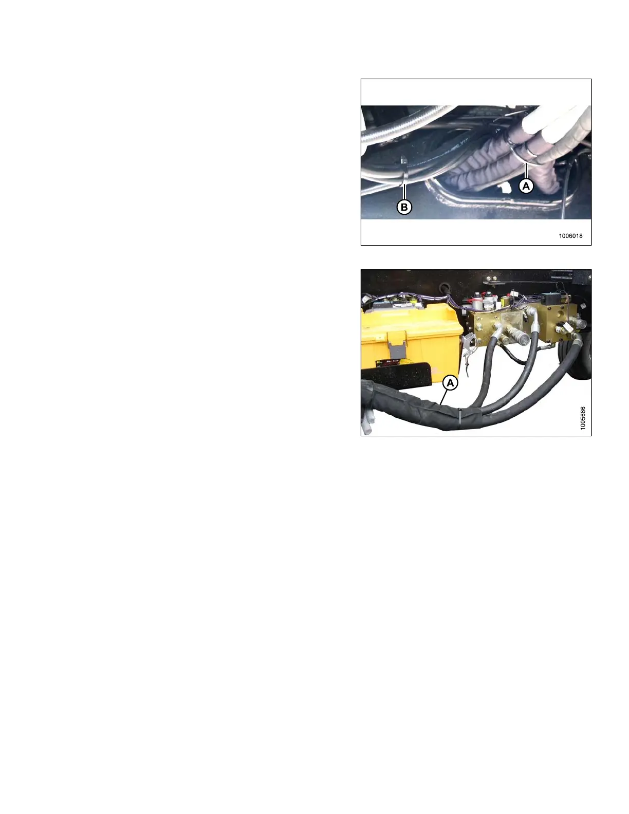
25. Bundle traction drive hoses and secure with two plastic
cable ties (A) at 200 mm (7-3/4 in.) intervals from the
frame opening.
26. Bundle smaller hoses and secure with two plastic
cable ties (B) at 150 mm (6 in.) intervals from the
frame opening.
Figure 3.71: Hose Routing
27. Position h
ose bundle (A) from the valve blocks on the
left-hand
side of the frame onto the tire.
28. Note rout
ing of e lectrical harness.
IMPORTAN
T:
The electrical harness must be routed on the
topside of the hose bundle and on the outside
of the hose support to prevent chafing of the
electrical wires when the windrower is operating
with a header.
Figure 3.72: Hose Routing
147962 57 Revision A