Preparation for Monitoring ECG Monitoring ECG, Arrhythmia, ST and QT
7 - 8 TM80 Telemetry Monitor Operator’s Manual
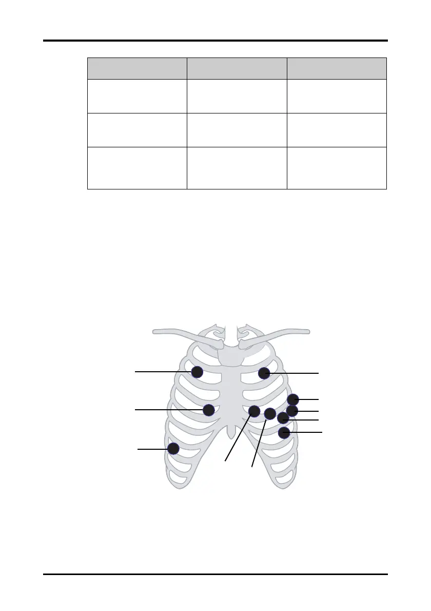
7.3.4.3 Standard 6-Leadwire Electrode Placement
For a 6-lead placement, use the positions from the 5-lead diagram above but with two
chest leads. The two chest leads are Va and Vb per AHA standard, and are Ca and Cb per
IEC standard. Va (Ca) and Vb (Cb) can be positioned at any two of the V1 (C1) to V6 (C6)
positions shown in the chest electrode diagram below. The default position of Va and Ca
is V1 and C1 respectively. The default position of Vb and Cb is V2 and C2 respectively
The positions of Va (Ca) and Vb (Cb) can also be placed at a proper position according to
the clinician’s needs.
LL (red) F (green) On the patient’s lower left
chest wall within the ribcage
frame.
RL (green) N (black) On the patient’s lower right
abdomen within the ribcage
frame.
V (brown) C (white) V-lead (C-lead) position
depicted in the figure above,
or the V (C) electrode should
be placed by a clinician.
AHA IEC Electrode Placement
V2 (C2)
V3(C3)
RA (R)
RL (N)
V1 (C1)
LL (F)
V6 (C6)
V5 (C5)
V4 (C4)
LA (L)