Moog ACV with CANopen bus interface 6 Signal routing and scaling
Drive transducer interface
B99224-DV018-D-211, Rev. A, October 2018 85
6.3.14.5 Example 4: Adjust transducer interface with scaling
1. Select the transducer interface which is intended to be adjusted.
Therefore set the <InterfaceNumber> (0x6201).
2. Define the input signal for the transducer interface with the input parameter address.
Get the index, sub-index and parameter length in bits from the object dictionary or from the parameter
description.
For example, the analog input 2 <ActualValue2> (0x6211) should be used as input:
Build the address value in the following manner:
Write the result 0x00030010 in the parameter <TransducerPort> (0x4032).
3. Check transducer interfaces <Sign> (0x6203) and change value (1 or –1) if needed.
4. Set transducer interface <Type> (0x6202) to 2 (pressure transducer).
5. Set the <PressureOffset> (0x6223) to 0.
6. Define the scaling of the linear function by using two points with their coordinates
(x
1
,x
2
, y
1
, y
2
). The y values correspond to the output (normally the pressure) and the x values corre-
spond to the mapped input signal.
x
1
: <MinimumTransducerSignal> (0x6224)
x
2
: <MaximumTransducerSignal> (0x6225)
y
1
: <MinimumPressure> (0x6220)
y
2
: <MaximumPressure> (0x6221)
Index: 0x3214
Index MSB: 0x32
Index LSB: 0x14
Sub-index: 0x00
Parameter bit length: 0x10
Only parameters with a bit length of 0x10 are allowed to be mapped!
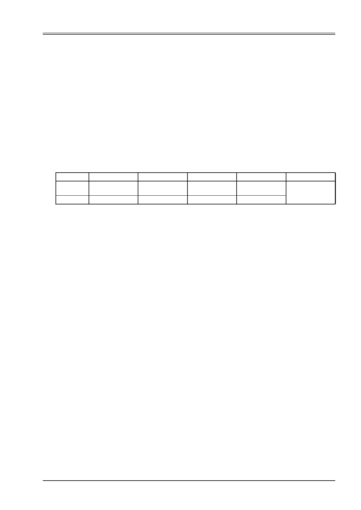
Byte3210Result
Description
MSB LSB Parameter bit
length: 0x10
Example 0x32 0x14 0x00 0x10 0x32140010