Moog ACV with CANopen bus interface 5 Device control
Device state machine (DSM)
B99224-DV018-D-211, Rev. A, October 2018 46
5.2 Device state machine (DSM)
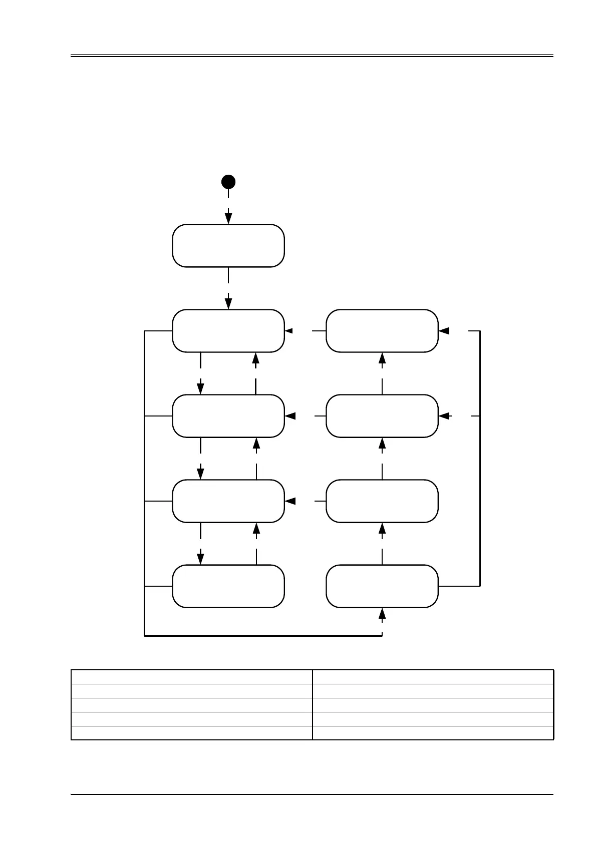
The device state machine (DSM) describes the states of the servo valve and the transitions between them.
Any state represents a certain internal and external behavior. State changes result from DSM input and other
events (for example switching on the supply voltage or on the appearance of a device fault). The current de-
vice state can be read by means of the <StatusWord> (0x6041) (bits 0…3 of the status word indicate the de-
vice condition).
Figure 19: Device state machine
'NOT READY'
#ControlWord# MHD = 000
<StatusWord> RMHD = 0000
'INIT'
#ControlWord# MHD = 000
<StatusWord> RMHD = 1000
'DISABLED'
#ControlWord# MHD = xx1
<StatusWord> RMHD = 1001
'HOLD'
#ControlWord# MHD = x11
<StatusWord> RMHD = 1011
'ACTIVE'
#ControlWord# MHD = 111
<StatusWord> RMHD = 1111
'FAULT HOLD'
<StatusWord> RMHD = 0011
'FAULT REACTION'
<StatusWord> RMHD = 0111
TR1
TR2
TR3
TR4 TR5
TR6
TR7
TR8
TR9
TR10
TR11
TR0
TR14
'FAULT DISABLED'
<StatusWord> RMHD = 0001
TR15
'FAULT INIT'
<StatusWord> RMHD = 0000
TR16
TR13
TR12
<StatusWord> (0x6041) #ControlWord#
(Bit 3) R: Ready (Bit 3) R: Reset fault
(Bit 2) M: Active (Bit 2) M: Active
(Bit 1) H: Hold (Bit 1) H: Hold
(Bit 0) D: Disabled (Bit 0) D: Disabled