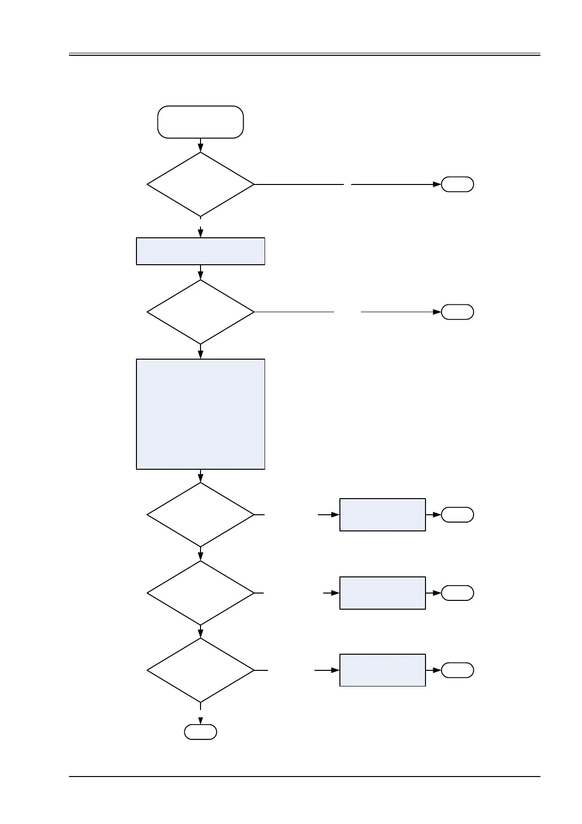
Fault occurs with a specific
fault code
Device state machine (DSM)
state change to
’NOT READY’
Device state machine (DSM)
state change to
’FAULT HOLD’
Device state machine (DSM)
state change to
’FAULT DISABLED’
127 (FAULT STOP)
3 (FAULT HOLD)
2 (FAULT DISABLED)
yes
No
0 (NONE)
1 (EMERGENCY)
Continue
Continue
Continue
Set fault code in <FaultStatus> (0x2831) and
<RetainFaultStatus> (0x2834)
Set <ErrorRegister> (0x1001)
Save the last eight
fault and error codes in
<StandardErrorField> (0x1003)
<NumberOfErrors> (0x1003)
Save last eight error strings
<FaultReactionDescription> (0x2832)
<FaultHistoryNumber> (0x2833)
Send emergency message with fault and
error code, error register and timestamp
Continue
Continue
Continue
Fault reaction
defined in
<Type> (0x2830)
[FaultCode+1]
New
fault code ?
Fault reaction
defined in
<Type> (0x2830)
[FaultCode+1]
Fault reaction
defined in
<Type> (0x2830)
[FaultCode+1]
Fault reaction
defined in
<Type> (0x2830)
[FaultCode+1]