Moog ACV with CANopen bus interface 7 Servo valve functions
Pressure controller
B99224-DV018-D-211, Rev. A, October 2018 172
7.5.9.1 Object 0x2303[N]: Ramp slope
If a 100 % step is set as input, the ramp output needs <RampSlope> (0x2303) milliseconds to reach the
100 % ramp output.
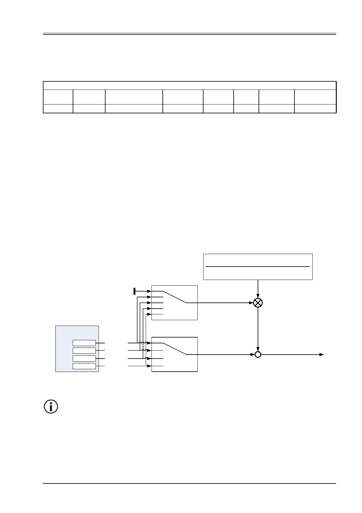
7.5.10 Pressure transducer selection
The actual value for the pressure controller will be routed through the four possible transducer interfaces. Two
different pressure control types depending on the pressure transducer selection are possible:
• Normal pressure control
Only one pressure signal from the transducer interface <ActiveTransducerInterfaceAreaA> (0x230D[N])
is fed to the pressure controller. The <ActiveTransducerInterfaceAreaB> (0x230F[N]) is set to zero.
• Differential pressure control
Two pressure signals from the transducer interfaces are fed to the pressure controller.
One from <ActiveTransducerInterfaceAreaA> (0x230D[N]) for the pressure in the servo valve port A and
one from the transducer interface <ActiveTransducerInterfaceAreaB> (0x230F[N]) for the pressure in the
servo valve port B.
For a differential cylinder, the resultant force can be calculated with the port pressures and the bore (A)
and annulus (B) areas. For this the parameters <CylinderPistonDiameter> (0x585F),
<CylinderRodDiameterA> (0x585D) and <CylinderRodDiameterB> (0x585E) are used.
Figure 81: Pressure transducer selection
ValvePressureControl
Index Sub-index Parameter name Data type Access
Per-
sistence Value range Default
0x2303 N=1…16 RampSlope UINT16 rw Y UINT16 0
Pressure actual value path
Interface 1
Interface 2
Interface 3
Interface 4
<ActualValue4>
(0x6113)
<ActualValue3>
(0x6112)
<ActualValue2>
(0x6111)
<ActualValue1>
(0x6110)
<ActiveTransducerInterfaceAreaA>
(0x230D[N])
<ActiveTransducerInterfaceAreaB>
(0x230F[N])
1
2
3
4
0
1
2
3
4
<CylinderPistonDiameter>
(0x585F)
<CylinderRodDiameterB>
(0x585E)
<CylinderRodDiameterA>
(0x585D)
<CylinderPistonDiameter>
(0x585F)
() )
))((
(
22
22
-
-
+
-
Set the parameter <ActiveTransducerInterfaceAreaB> (0x230F[N]) to 0 to switch off the differen-
tial pressure control.