Moog ACV with CANopen bus interface 5 Device control
Device state machine (DSM)
B99224-DV018-D-211, Rev. A, October 2018 52
5.2.2.5 Error output pin
The error output (digital output 1) is used to indicate fault states (negative logic) according to the Device
Profile Fluid Power.
• Digital output 1 is set to 1 on power on (TR1) of the servo valve.
• When a fault is detected (TR8) the digital output 1 is set to 0 to indicate a fault (negative logic).
• When a fault state is left (TR10, TR11) the digital output 1 is set to 1.
To enable this behavior on the digital output 1, the parameter <DigitalOutputType1> (0x2420) must be set
to 2.
Chapter "6.8.2 Object 0x5E41: Digital output configuration", page 101
5.2.3 Object 0x6041: Status word
The bit-coded <StatusWord> (0x6041) indicates the current device status.
Value description
Bits 0, 1, 2, 3: 'DISABLED', 'HOLD', 'ACTIVE', 'READY'
These bits indicate the state of the device state machine (DSM).
Chapter "5.2 Device state machine (DSM)", page 46
Bit 4: Indicates that bit <Local> (0x604F) is set
The <LocalControlWord> (0x4040) is the active control word.
Chapter "5.1 Local mode", page 43
Device
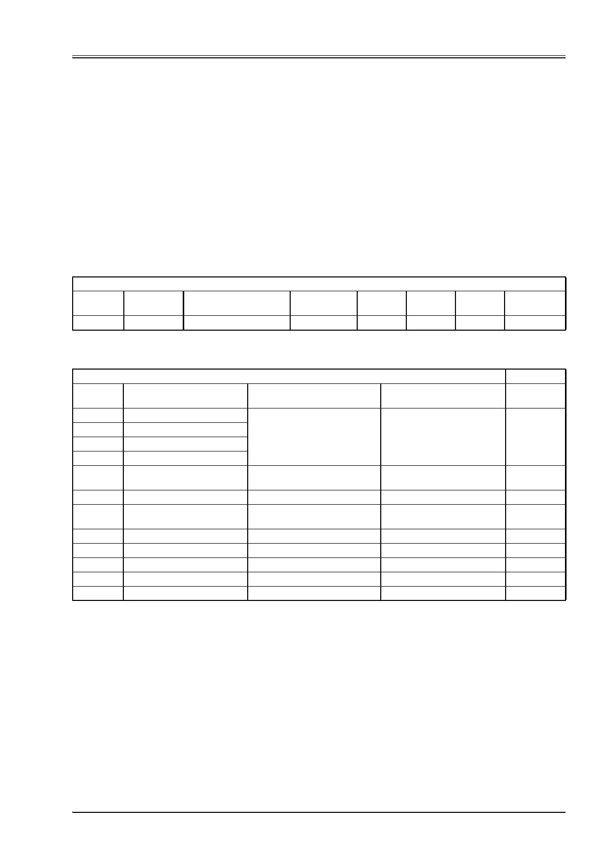
Index Sub-index Parameter name Data type Access
Persis-
tence
Value
range Default
0x6041 0 StatusWord UINT16 ro - UINT16 None
<StatusWord>
Bit <StatusWord> bit
<Control Mode> (0x6043) is set
to 1…4, 7…14
<Control Mode> (0x6043) is
set to 5 Specification
0 Bit Disabled (D) CiA 408
1 Bit Hold (H)
2 Bit Active (M)
3 Bit Ready (R)
4 Indicates that bit <Local>
(0x604F) is set
CiA 408
5…7 Reserved
8 <ControlMode> (0x6043)
specific
Reserved Pressure controller effective CiA 408
9 Ramp running CiA 408
10 Limit touched (c) CiA 408
11 Control deviation CiA 408
12…14 Reserved
15 Ramp frozen Moog DCV
Table 31: Possible values of parameter <StatusWord> (0x6041)