Moog ACV with CANopen bus interface 6 Signal routing and scaling
Analog inputs
B99224-DV018-D-211, Rev. A, October 2018 86
6.4 Analog inputs
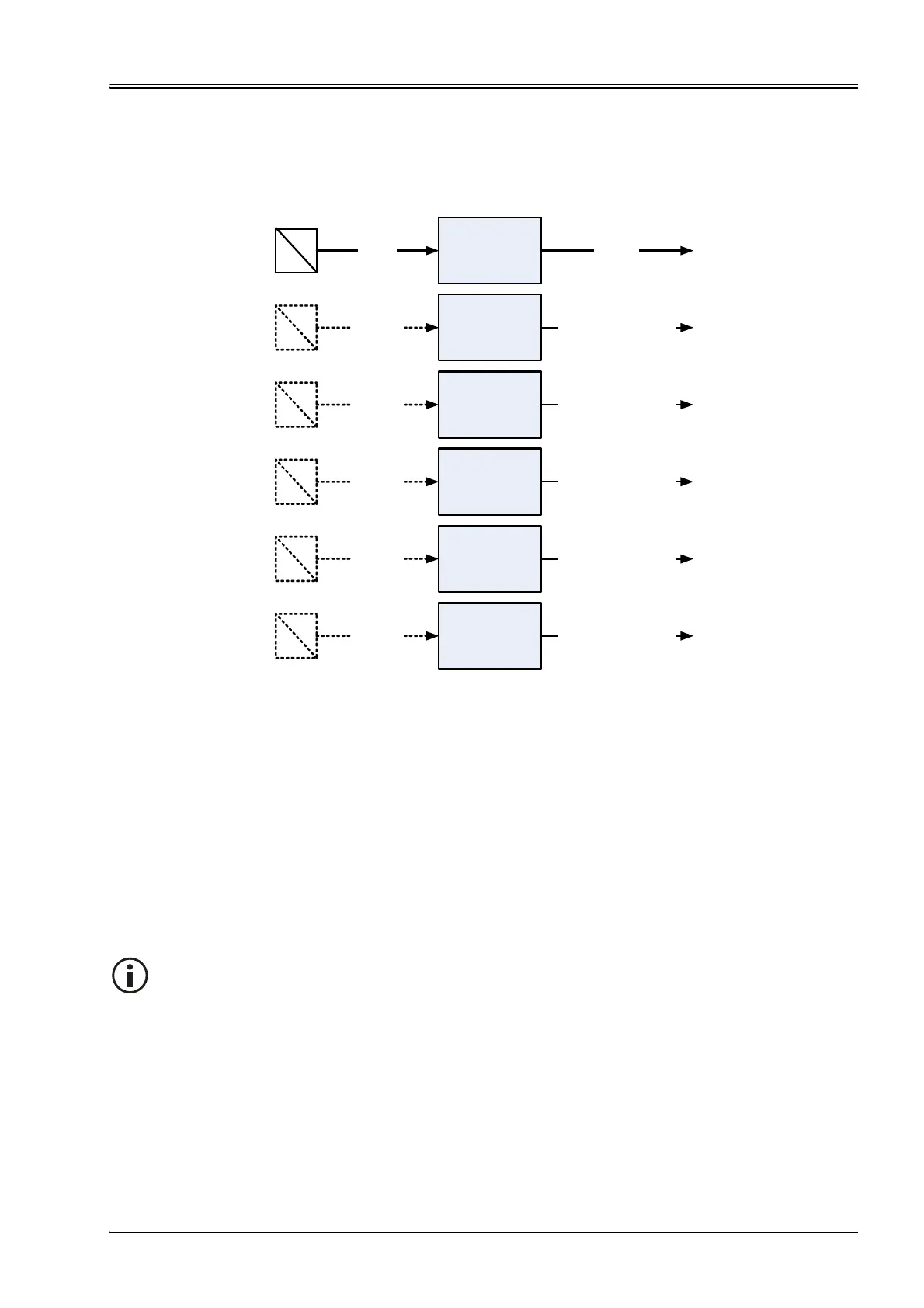
The following figure shows the available inputs and the physical connector names. All analog to digital con-
verters have the same resolution of 12 bit.
Figure 34: Analog inputs
Document CA63420-001 "User Manual Electrical Interfaces".
The analog input 0 is intended for the spool position setpoint value and the analog input 1 is intended for the
pressure setpoint value. The analog inputs 0 and 1 will only be routed to the demand value generators, if the
<DeviceMode> (0x6042) is set to 2 (setpoint input locally). The setpoint values are provided by the field bus, if
the <DeviceMode> (0x6042) is set to 1 (setpoint input via bus). In this case the analog inputs 0 and 1 can be
used as additional inputs for external transducers.
Chapter "6.2.3 Spool position setpoint value path", page 59
An external transducer on analog input 0, 1, 2, 3 or 4 can be scaled and mapped as input for the controller by
using the transducer interface.
Chapter "6.3.9 Transducer interface definition", page 74
p
u
Analog input 2
Analog input 3
Analog input 4
Analog input 1
Analog input 0
Internal pressure
transducer in
port A
Connector
X1
Connector
X1
Connector
X5
Connector
X7
p
u
p
u
p
u
p
u
Connector
X6
pA
u
<Value>
(0x3404)
<AnaInpActualValue0>
(0x3204)
<AnaInpActualValue1>
(0x320C)
<AnaInpActualValue2>
(0x3214)
<AnaInpActualValue4>
(0x3224)
<AnaInpActualValue3>
(0x321C)
Internal
Chapter 6.4.6
Chapter 6.4.1
Chapter 6.4.2
Chapter 6.4.3
Chapter 6.4.4
Chapter 6.4.5
The analog inputs 0 and 1 are only effective as setpoint value inputs, if the <DeviceMode>
(0x6042) is set to 2 (setpoint input locally).