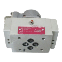
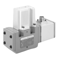
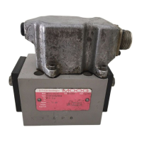
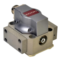
Moog ACV with CANopen bus interface Table of contents
B99224-DV018-D-211, Rev. A, October 2018 x
7.5.21.1 Object 0x230C[N]: Hydraulic capacity................................................... 187
7.5.21.2 Object 0x231C: Sys Pressure Reference.............................................. 187
7.6 Spool position (Q) / pressure (P) switchover........................................................................ 187
7.6.1 Object 0x586C[N]: pQ switching mode ...................................................................... 188
7.6.1.1 Object 0x3300: Demand value pilot ...................................................... 188
7.6.2 Minimum criterion in positive direction (switching mode 0) ........................................ 188
7.6.3 Minimum criterion in both directions (switching mode 1)............................................ 189
7.6.4 Force exceeded in both directions (switching mode 2) .............................................. 190
7.7 Axis position setpoint conditioning / demand value generator .......................................... 191
7.7.1 Object 0x6610: Position demand value...................................................................... 191
7.7.2 Object 0x561E: Velocity demand value...................................................................... 191
7.7.3 Object 0x5616: Acceleration demand value............................................................... 192
7.7.4 Axis position trajectory generator ............................................................................... 193
7.7.4.1 Object 0x5700: Trajectory type ............................................................. 194
7.7.4.2 Object 0x5703: Maximum velocity......................................................... 194
7.7.4.3 Object 0x5702: Maximum acceleration ................................................. 194
7.7.5 Axis position demand value filter................................................................................ 194
7.7.5.1 Object 0x582A: Demand value filter time constant ............................... 194
7.7.6 Axis position manual movement................................................................................. 195
7.7.6.1 Object 0x5614: Manual maximum speed .............................................. 195
7.8 Axis position controller .......................................................................................................... 195
7.8.1 Object 0x6601: Actual value....................................................................................... 196
7.8.2 Object 0x582B: Demand filter output ......................................................................... 196
7.8.3 Object 0x6650: Control deviation ............................................................................... 196
7.8.4 Object 0x552A: Kp output .......................................................................................... 196
7.8.5 Object 0x552A: Kp T1 output ..................................................................................... 196
7.8.6 Object 0x552C: Ki output ........................................................................................... 197
7.8.7 Object 0x552B: Kd output .......................................................................................... 197
7.8.8 Object 0x552E: Velocity feedforward output .............................................................. 197
7.8.9 Object 0x552F: Acceleration feedforward output ....................................................... 197
7.8.10 Object 0x5530: Velocity feedback output ................................................................... 197
7.8.11 Object 0x5531: Acceleration feedback output............................................................ 198
7.8.12 Object 0x550F: Controller output ............................................................................... 198
7.8.13 Sample frequency ...................................................................................................... 198
7.8.13.1 Object 0x553F: Sample frequency divider ............................................ 198
7.8.14 Axis position transducer selection .............................................................................. 199
7.8.14.1 Object 0x6602: Actual value reference ................................................. 199
7.8.15 Axis position synchronisation ..................................................................................... 200
7.8.15.1 Object 0x5829: Synchronisation gain.................................................... 200
7.8.15.2 Object 0x5830: Number of axis to synchronize ..................................... 200
7.8.16 Proportional element with first order lag element....................................................... 200
7.8.16.1 Object 0x5501: Proportional gain .......................................................... 201
7.8.16.2 Object 0x5508: Time constant............................................................... 201
7.8.17 Integral element..........................................................................................................201
7.8.17.1 Object 0x5504: Integral gain ................................................................. 201
7.8.17.2 Object 0x5511: Integral inner range ...................................................... 202
7.8.17.3 Object 0x5505: Integral outer range...................................................... 202
7.8.17.4 Object 0x5513: Integral limit.................................................................. 202


 To Next Page