7 Special functions
●
3250
h
:05
h
: The bit combination applied to the outputs is stored in this subindex.
●
3250
h
:08
h
: For activating the Output Routing.
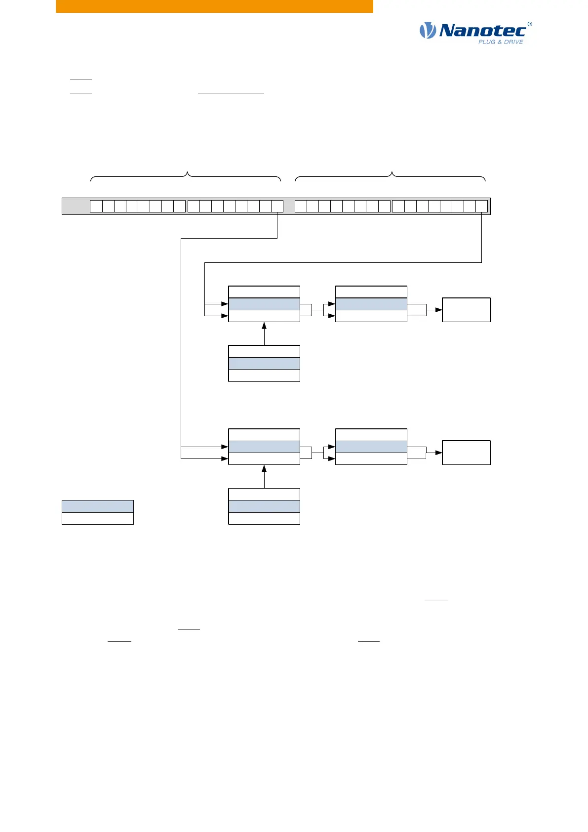
7.1.3.4 Computation of the outputs
Example for calculating the bits of the outputs:
Value of Output
Pin1
Bit0
Bit15
Bit16Bit31
60FEh
Standard setting
Alternative
Range of normal
output pins
Range of output pins
with special function
Value of
brake
Bit in 3250h:2
1: Do invert logic
0: Do not invert logic
Bit in 3250h:2
1: Do invert logic
0: Do not invert logic
Bit in 3250h:3
1: Value forced
0: Value not forced
Bit in 3250h:3
1: Value forced
0: Value not forced
Bit in 3250h:4
1: Value = 1
0: Value = 0
Bit in 3250h:4
1: Value = 1
0: Value = 0
7.1.3.5 Output Routing
Principle
The "Output Routing Mode" assigns an output a signal source; a control bit in object 60FE
h
:01
h
switches the
signal on or off.
The source is selected with 3252
h
:01 to 05 in the "high byte" (bit 15 to bit 8). The assignment of a control bit
from object 60FE
h
:01
h
is performed in the "low byte" (bit 7 to bit 0) of 3252
h
:01
h
to 05 (see following figure).
Version: 2.0.1 / FIR-v1650 85