7 Special functions
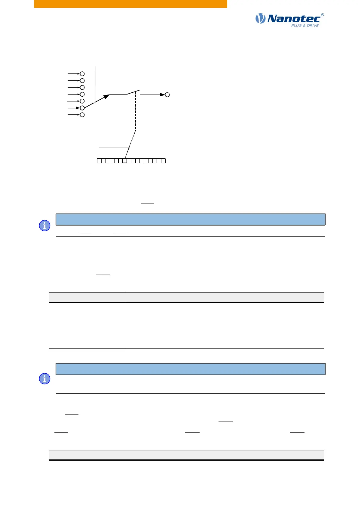
Signal
sources
Selection of
source with
3252:NN high byte
Bits of 60FE
h
:01
Selection of
control bit with
3252:NN low byte
Ouput
Activation
This mode is activated by setting object 3250
h
:08
h
(Routing Enable) to 1.
Note
Entries 3250
h
:01
h
to 3250:04
h
then have no function until "Output Routing" is switched off again.
Routing
The subindex of object 3252
h
determines which signal source is routed to which output. The output
assignments are listed in the following:
Subindex 3252
h
Output Pin
01
h
Configuration of the PWM output (software PWM)
02
h
Configuration of output 1
03
h
Configuration of output 2 (if available)
04
h
Configuration of output 3 (if available)
05
h
Configuration of output 4 (if available)
Note
The maximum output frequency of the PWM output (software PWM) is 2 kHz. All other outputs can
only produce signals up to 500 Hz.
Subindices 3252
h
:01
h
to 05
h
are 16 bits wide, whereby the high byte selects the signal source (e.g., the
PWM generator) and the low byte determines the control bit in object 60FE
h
:01.
Bit 7 of 3252
h
:01
h
to 05 inverts the controller from object 60FE
h
:01. Normally, value "1" in object 60FE
h
:01
switches on the signal; if bit 7 is set, the value "0" switches on the signal.
Number in 3252:01 to 05
00XX
h
Output is always "1"
Version: 2.0.1 / FIR-v1650 86