Trainee Guide TR-L2-M2000
Level 2 Maintenance Training – M2000 Dispensing Systems 1-2-11 P/N 73-0018-00 (Revision B)
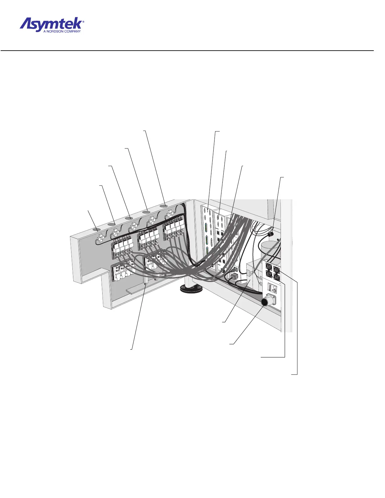
Diagram Sheet 1-1-4
Rear Cabinet Features
U
/D
Lef
t
U/D
Right
201D
I/O
Interface
201W
I/O
Con
fig.
Pneu. Solenoids
Elec. S
olenoids
U/D
Fuse
Valve Speed
Encap.
Valve1
Valve 2
Lights
12 VDC
E. Stop
Main Power
M
a
i
n
P
o
w
e
r
E
.
S
t
o
p
Heater Control
Anafaze
RS
-232
Scale P
ower
Safety
Conveyor
Doors
Needle
H
eater
24
VDC
Fuse
Fans
Config.
H
eater
Pow
er
TC1 TC2 TC3 TC
(11) Tensionator Air
Gauge and Regulator
(12) Tooling Air Gauge
and Regulator
(13) Fluid Air Gauge and
Re
ulator
(14) Valve Air Gauge and Regulator
(3) Heater Relay Module
(2) Temperature Controller Module
(1) Conveyor Controller Module (201W)
(8) 24/48 Power Suppl
(7) Main Power Inlet
(6) FSL Upstream/Downstream
Connectors
(5) SMEMA Upstream/Downstream
Connectors
(4) Moritex Light
Source (option)
(10) Cooling Air
Gauge and
Regulator (optional)
(9) High Pressure Relief Valve
 Loading...


