EasyManua.ls Logo

Omron Sysmac NY-series User Manual

Omron Sysmac NY-series
744 pages
To Next Page IconTo Next Page
To Previous Page IconTo Previous Page
Page #179 background imageLoading...
Page #179 background image
Precautions for Correct Use
If 3: _mcCurrentDirection (Current direction) is specified for Direction, operation is in the same
command direction as the previous motion. Therefore, depending on the instructions that are
used together
, the direction may not be the same as the direction that was specified with the
input to the motion control instruction for the previous motion.
When you specify 3: _mcCurrentDirection (Current direction), check the current direction with
Dir.Posi (Positive Direction) and Dir.Nega (Negative Direction) in the Axis Variable.
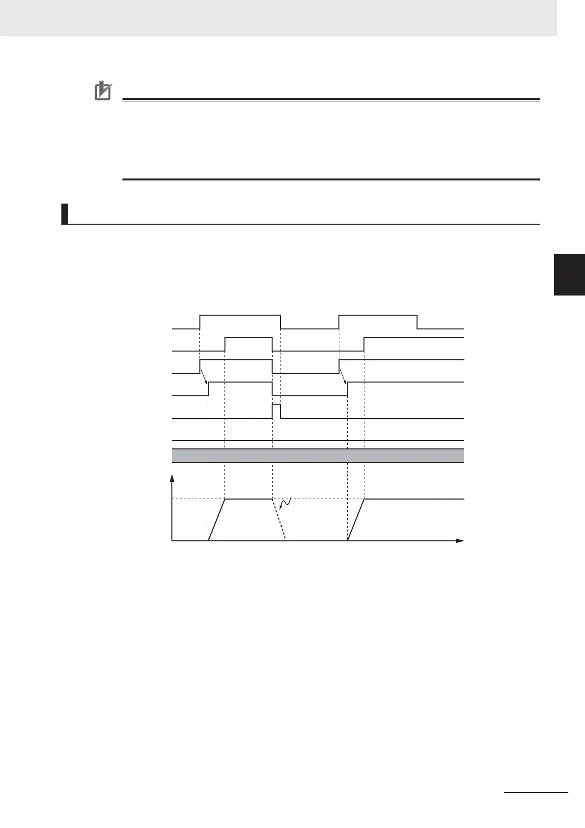
Timing Charts
Busy (Executing) changes to TRUE at the same time as Execute changes to TRUE. Active (Control-
ling) changes to TRUE in the next period.
InV
elocity (Target Velocity Reached) changes to TRUE when Velocity (Target Velocity) is reached.
If another instruction aborts this instruction, CommandAborted changes to TRUE and Busy (Execut-
ing), Active (Controlling), and InVelocity (Target Velocity Reached) change to FALSE.
Time
Decelerates to a stop
when another instruction
causes an error.
Target velocity
Velocity
Busy
CommandAborted
InVelocity
Error
16#0000
Error
ID
Execute
Active
The InV
elocity (Target Velocity Reached) output variable indicates when the velocity has reached the
same velocity for this instruction and the re-executed motion control instruction. Therefore, after
InVelocity (Target Velocity Reached) changes to TRUE, even if the velocity is changed by the override
factor, InVelocity (Target Velocity Reached) will not change to FALSE.
If the override factor changes before InVelocity (Target Velocity Reached) changes to TRUE,
InVelocity (Target Velocity Reached) will change to TRUE when the new target velocity is reached.
You can specify Acceleration (Acceleration Rate), Deceleration (Deceleration Rate) and Jerk as input
variables.
When the Velocity (Target Velocity) is 0 and the instruction is executed, the axis will enter continuous
operation without motion.
The following chart shows an operation example of when Velocity (Target Velocity) is 0.
3 Axis Command Instructions
3-91
NY-series Motion Control Instructions Reference Manual (W561)
MC_MoveVelocity
3
Function

Table of Contents

Question and Answer IconNeed help?

Do you have a question about the Omron Sysmac NY-series and is the answer not in the manual?

Omron Sysmac NY-series Specifications

General IconGeneral
CategoryControl Unit
Operating Temperature0 to 55 °C
Power Supply Voltage24 VDC
Power Supply24 VDC
Product SeriesNY-series
CPUIntel Atom or Intel Core i7
Programming LanguagesIEC 61131-3 (LD, FBD, ST, SFC)
Memory (Program)Up to 64 MB
Ethernet Ports2
EtherNet/IP Ports2 ports (built-in)
EtherCAT Master Ports1
EtherCATYes
Motion ControlSupported
SafetyYes
Built-in I/ONo
Relative Humidity10 to 90% (non-condensing)
Vibration Resistance5 to 8.4 Hz: 3.5 mm; 8.4 to 150 Hz: 9.8 m/s²
Shock Resistance147 m/s²
Power ConsumptionVaries by model
CertificationsCE, cULus, RCM, KC, EAC

Summary

Introduction to Motion Control Instructions

Variables and Instructions

Axis Command Instructions

MC_Power

Explains the MC_Power instruction for making a Servo Drive ready to operate.

MC_MoveJog

Explains the MC_MoveJog instruction for jogging an axis according to the specified target velocity.

MC_Home

Explains the MC_Home instruction for operating the motor to determine home.

MC_HomeWithParameter

Explains the MC_HomeWithParameter instruction for setting homing parameters and operating the motor to determine home.

MC_Move

Explains the MC_Move instruction for performing absolute positioning or relative positioning.

MC_MoveAbsolute

Explains the MC_MoveAbsolute instruction for moving the axis to a specified absolute target position.

MC_MoveRelative

Explains the MC_MoveRelative instruction for moving the axis the specified travel distance.

MC_MoveVelocity

Explains the MC_MoveVelocity instruction for performing velocity control.

MC_MoveZeroPosition

Explains the MC_MoveZeroPosition instruction for positioning to an absolute position of 0.

MC_Stop

Explains the MC_Stop instruction for decelerating an axis to a stop.

MC_ImmediateStop

Explains the MC_ImmediateStop instruction for stopping an axis immediately according to the specified stopping mode.

MC_CamIn

Explains the MC_CamIn instruction to start cam operation using a specified cam table.

MC_GearIn

Explains the MC_GearIn instruction to specify the gear ratio and start gear operation.

MC_GearInPos

Explains the MC_GearInPos instruction to perform electronic gear operation with specified gear ratio.

MC_MoveLink

Explains the MC_MoveLink instruction for positioning in sync with the specified master axis.

MC_TorqueControl

Explains the MC_TorqueControl instruction to control torque using the Torque Control Mode.

MC_SetTorqueLimit

Explains the MC_SetTorqueLimit instruction to limit torque output from the Servo Drive.

MC_TouchProbe

Explains the MC_TouchProbe instruction to record axis position when a trigger signal occurs.

MC_SyncMoveVelocity

Explains the MC_SyncMoveVelocity instruction for outputting target velocity in CSV Mode.

MC_SyncMoveAbsolute

Explains the MC_SyncMoveAbsolute instruction to cyclically output target positions.

MC_Reset

Explains the MC_Reset instruction to clear axis errors.

MC_DigitalCamSwitch

Explains the MC_DigitalCamSwitch instruction to turn a digital output ON or OFF based on axis position.

Axes Group Instructions

Common Command Instructions

Related product manuals