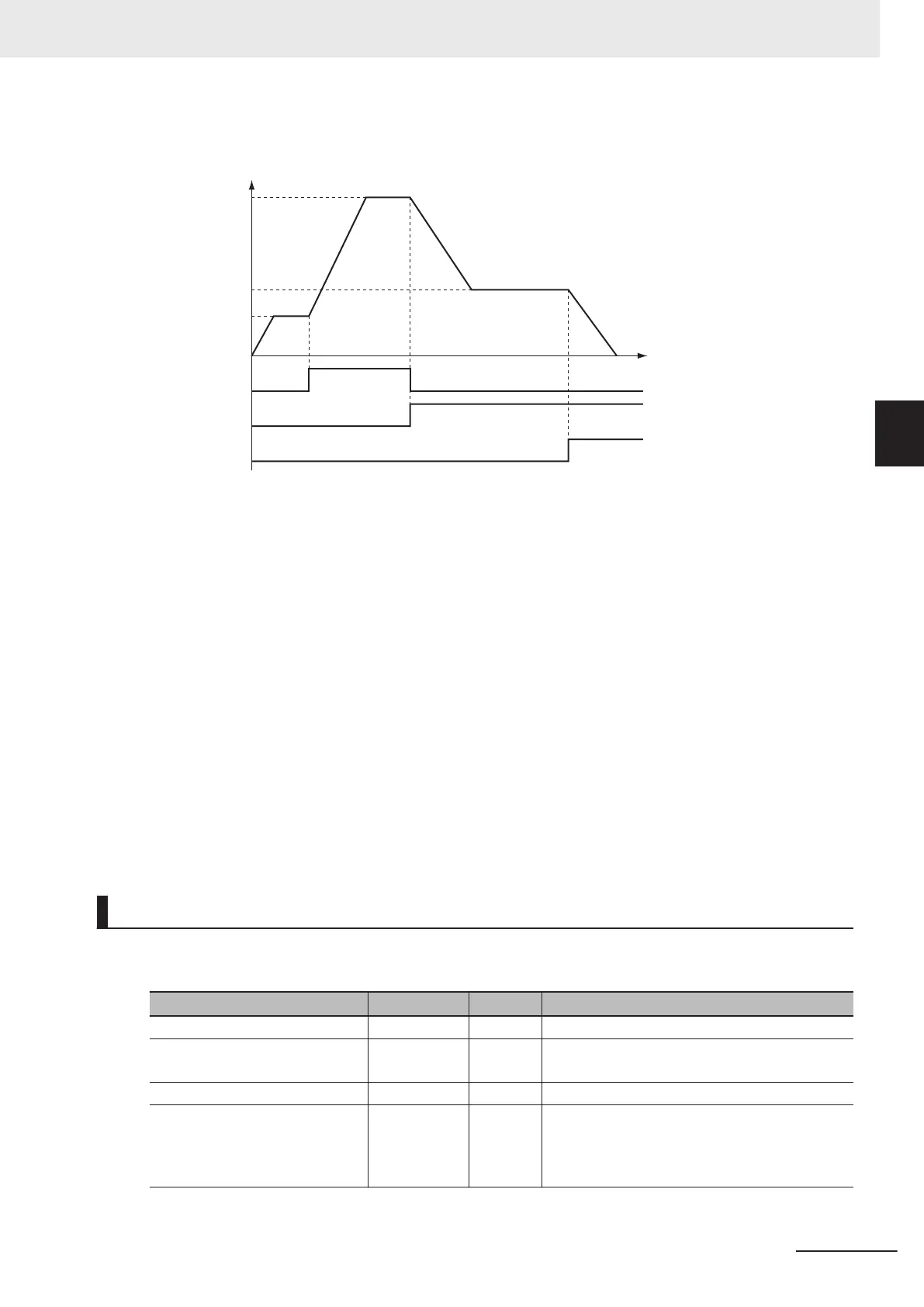
Operation Pattern
Sensor2
Sensor3
First velocity
Second velocity
Third velocity
Stop comm
and
Time
Velocity
1 Starting Velocity Control
Sensor 1 detects the insertion of liquid chemical. When it turns ON, velocity control starts for axis
1.
2 Changing to the Second Velocity
When the Sensor2 bit changes to TRUE, the override factor is set to 500% and the velocity is
changed.
3 Changing to the Third Velocity
When the Sensor3 bit changes to TRUE, the override factor is set to 200% and the velocity is
changed.
If both Sensor2 and Sensor3 are TRUE at the same time, the override factor is 200%.
4 Stopping Velocity Control
When the stop command (StopT
rig) changes to TRUE, the axis decelerates to a stop.
Ladder Diagram
Main Variables
Name Data type Default Comment
MC_Axis000 _sAXIS_REF --- Axis Variable for axis 1.
MC_Axis000.MFaultLvl.Active BOOL FALSE TRUE while there is a minor fault level error for
axis 1.
MC_Axis000.Details.Homed BOOL FALSE TRUE when home is defined for axis 1.
Pwr_Status BOOL FALSE This variable is assigned to the Status output
variable from the PWR instance of the
MC_Power instruction. This variable changes to
TRUE when the Servo is turned ON.
3 Axis Command Instructions
3-95
NY-series Motion Control Instructions Reference Manual (W561)
MC_MoveVelocity
3
Sample Programming