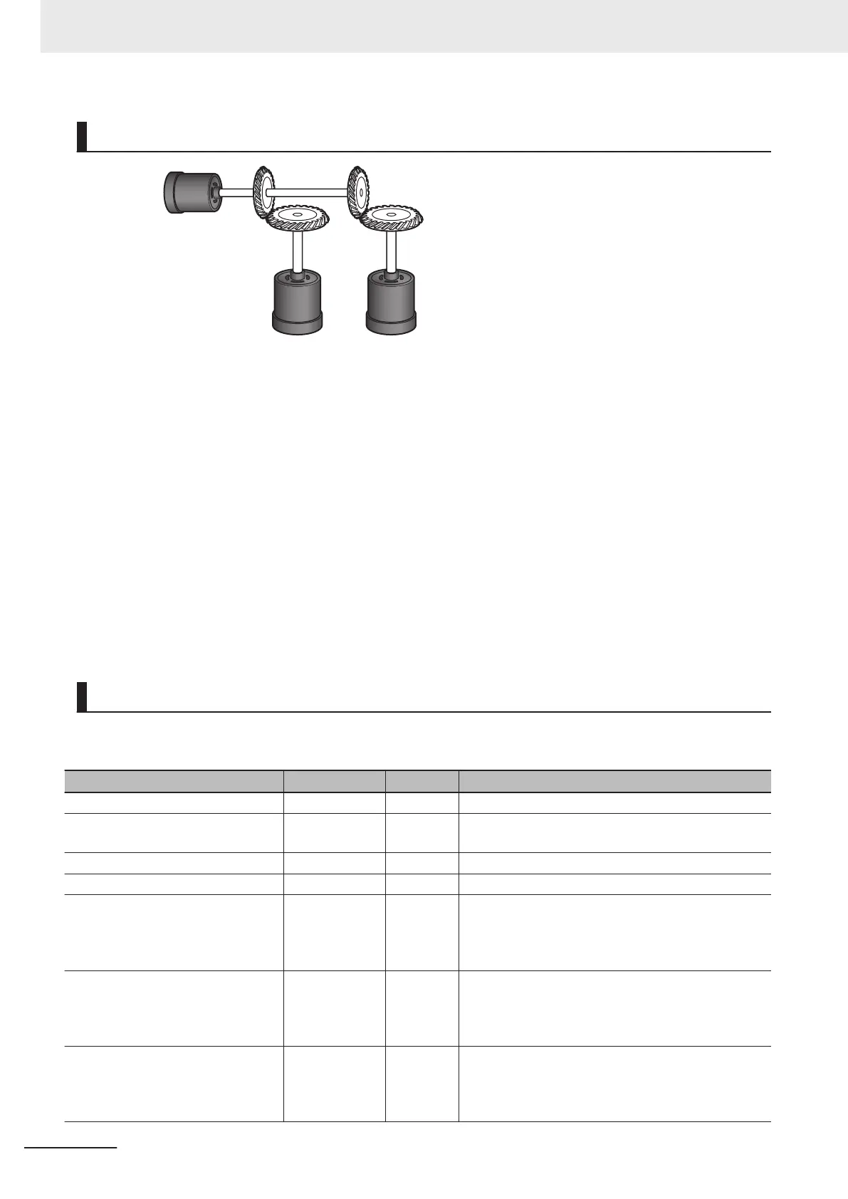
Operation Example
1 : 2
2 :
3
Axis 1
Axis 2
Axis 3
1 Starting the Master Axis
The master axis (axis 1) is an actual servo axis and it is operated with velocity control.
2 Executing the Slave Axes
When the actual velocity for the master axis reaches the target velocity
, gear operation is per-
formed so that the gear ratio of axis 2 (slave axis) is 1:2 and axis 3 (slave axis) is 2:3 against
the actual position of the master axis.
3 Stopping the Slave Axes
When the actual position of the master axis MC_Axis000.Act.Pos exceeds 1000.0, gear opera-
tion of axis 2 is ended and axis 2 decelerates to a stop with deceleration rate DecRate. Axis 3
continues gear operation.
Ladder Diagram
Main Variables
Name Data type Default Comment
MC_Axis000 _sAXIS_REF --- Axis Variable for the master axis, axis 1.
MC_Axis000.Act.Pos LREAL --- This variable gives the actual current position of axis
1.
MC_Axis001 _sAXIS_REF --- Axis Variable for the slave axis, axis 2.
MC_Axis002 _sAXIS_REF --- Axis Variable for the slave axis, axis 3.
Pwr1_Status BOOL FALSE This variable is assigned to the Status output varia-
ble from the PWR1 instance of the MC_Power in-
struction. This variable changes to TRUE when the
Servo is turned ON.
Pwr2_Status BOOL FALSE This variable is assigned to the Status output varia-
ble from the PWR2 instance of the MC_Power in-
struction. This variable changes to TRUE when the
Servo is turned ON.
Pwr3_Status BOOL FALSE This variable is assigned to the Status output varia-
ble from the PWR3 instance of the MC_Power in-
struction. This variable changes to TRUE when the
Servo is turned ON.
3 Axis Command Instructions
3-256
NY-series Motion Control Instructions Reference Manual (W561)