EasyManua.ls Logo

Omron Sysmac NY-series User Manual

Omron Sysmac NY-series
744 pages
To Next Page IconTo Next Page
To Previous Page IconTo Previous Page
Page #451 background imageLoading...
Page #451 background image
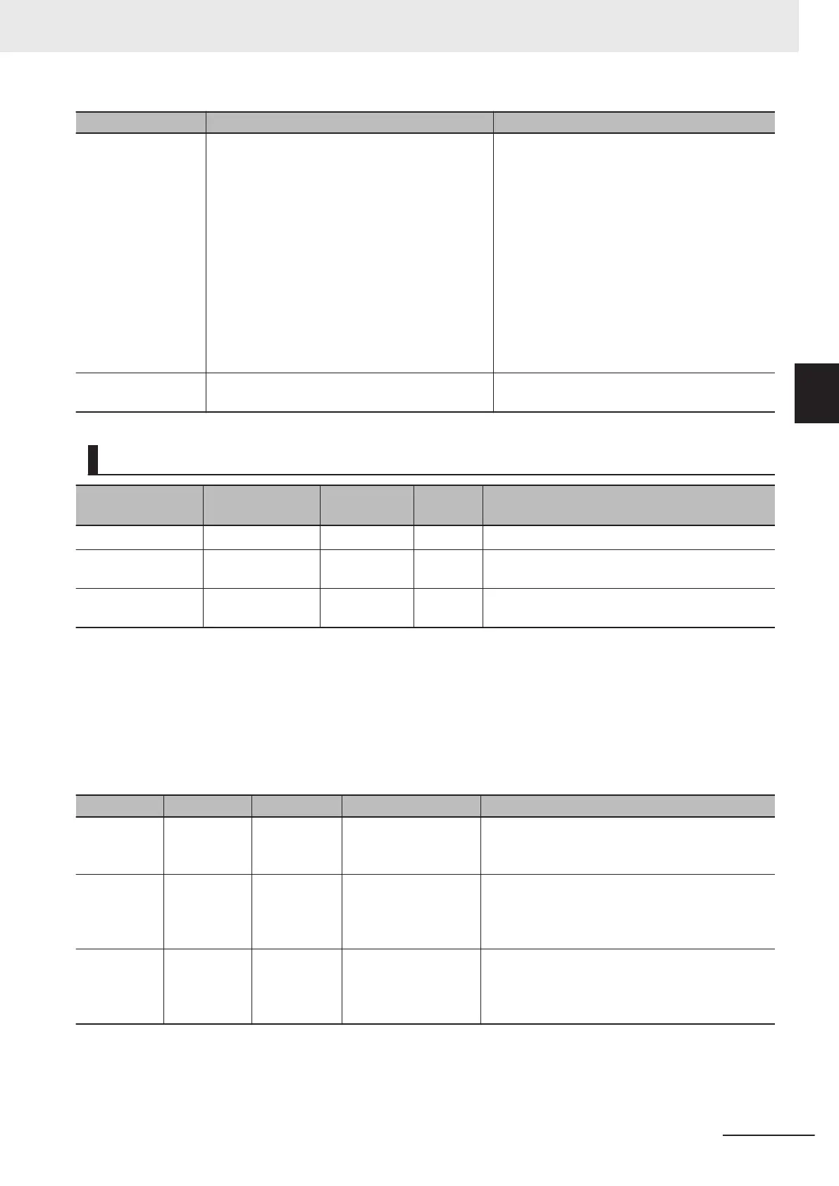
Name Timing for changing to TRUE Timing for changing to FALSE
CommandAborted
When this instruction is aborted because an-
other motion control instruction was executed
with the Buf
fer Mode set to Aborting.
When this instruction is canceled due to an er-
ror.
If StopMode is set to _mcImmediateStop,
when a change is made to a mode other than
CSP Mode during execution.
When the slave is disconnected.
When a slave communications error occurs
(except during process data communications).
When the MC_AbortTrigger instruction is exe-
cuted.
When Execute is TRUE and changes to
FALSE.
After one period when Execute is FALSE.
Error When there is an error in the execution condi-
tions or input parameters for the instruction.
When the error is cleared.
In-Out Variables
Name Meaning Data type
Valid
range
Description
Axis Axis _sAXIS_REF ---
Specify the axis.
*1
TriggerInput Trigger Input Con-
dition
_sTRIG-
GER_REF
---
Set the trigger condition.
*2
TriggerVariable Trigger Variable BOOL TRUE or
F
ALSE
Specify a trigger input variable when the Control-
ler Mode is specified for the trigger mode.
*1. Specify a user-defined Axis Variable that was created in the Axis Basic Settings of the Sysmac Studio (default: MC_Ax-
is*) or a system-defined axis variable name (_MC_AX[*]).
If you use Sysmac Studio version 1.29 or higher
, you can specify the system-defined axis variable name for AT specifi-
cation of a user-defined variable. This will allow you to specify the user-defined variable.
If you use Sysmac Studio version 1.28 or lower, do not specify any user-defined variable created in the variable table.
*2. Define a user-defined variable with a data type of _sTRIGGER_REF.
_sTRIGGER_REF
Name Meaning Data type Valid range Function
Mode Mode _eMC_TRIG-
GER_MODE
0: _mcDrive
1: _mcController
Specify the trigger mode.
0: Drive Mode
1: Controller Mode
LatchID Latch ID Se-
lection
_eMC_TRIG-
GER_LA
TCH
_ID
0: _mcLatch1
1: _mcLatch2
Specify which of the two latch functions to use in
Drive Mode.
0: Latch 1
1: Latch 2
InputDrive Trigger Input
Signal
_eMC_TRIG-
GER_IN-
PUT_DRIVE
0: _mcEncoderMark
1: _mcEXT
Specify the Servo Drive trigger signal to use in
Drive Mode.
0: Z-phase signal
1: External input
3 Axis Command Instructions
3-363
NY-series Motion Control Instructions Reference Manual (W561)
MC_TouchProbe
3
Variables

Table of Contents

Question and Answer IconNeed help?

Do you have a question about the Omron Sysmac NY-series and is the answer not in the manual?

Omron Sysmac NY-series Specifications

General IconGeneral
CategoryControl Unit
Operating Temperature0 to 55 °C
Power Supply Voltage24 VDC
Power Supply24 VDC
Product SeriesNY-series
CPUIntel Atom or Intel Core i7
Programming LanguagesIEC 61131-3 (LD, FBD, ST, SFC)
Memory (Program)Up to 64 MB
Ethernet Ports2
EtherNet/IP Ports2 ports (built-in)
EtherCAT Master Ports1
EtherCATYes
Motion ControlSupported
SafetyYes
Built-in I/ONo
Relative Humidity10 to 90% (non-condensing)
Vibration Resistance5 to 8.4 Hz: 3.5 mm; 8.4 to 150 Hz: 9.8 m/s²
Shock Resistance147 m/s²
Power ConsumptionVaries by model
CertificationsCE, cULus, RCM, KC, EAC

Summary

Introduction to Motion Control Instructions

Variables and Instructions

Axis Command Instructions

MC_Power

Explains the MC_Power instruction for making a Servo Drive ready to operate.

MC_MoveJog

Explains the MC_MoveJog instruction for jogging an axis according to the specified target velocity.

MC_Home

Explains the MC_Home instruction for operating the motor to determine home.

MC_HomeWithParameter

Explains the MC_HomeWithParameter instruction for setting homing parameters and operating the motor to determine home.

MC_Move

Explains the MC_Move instruction for performing absolute positioning or relative positioning.

MC_MoveAbsolute

Explains the MC_MoveAbsolute instruction for moving the axis to a specified absolute target position.

MC_MoveRelative

Explains the MC_MoveRelative instruction for moving the axis the specified travel distance.

MC_MoveVelocity

Explains the MC_MoveVelocity instruction for performing velocity control.

MC_MoveZeroPosition

Explains the MC_MoveZeroPosition instruction for positioning to an absolute position of 0.

MC_Stop

Explains the MC_Stop instruction for decelerating an axis to a stop.

MC_ImmediateStop

Explains the MC_ImmediateStop instruction for stopping an axis immediately according to the specified stopping mode.

MC_CamIn

Explains the MC_CamIn instruction to start cam operation using a specified cam table.

MC_GearIn

Explains the MC_GearIn instruction to specify the gear ratio and start gear operation.

MC_GearInPos

Explains the MC_GearInPos instruction to perform electronic gear operation with specified gear ratio.

MC_MoveLink

Explains the MC_MoveLink instruction for positioning in sync with the specified master axis.

MC_TorqueControl

Explains the MC_TorqueControl instruction to control torque using the Torque Control Mode.

MC_SetTorqueLimit

Explains the MC_SetTorqueLimit instruction to limit torque output from the Servo Drive.

MC_TouchProbe

Explains the MC_TouchProbe instruction to record axis position when a trigger signal occurs.

MC_SyncMoveVelocity

Explains the MC_SyncMoveVelocity instruction for outputting target velocity in CSV Mode.

MC_SyncMoveAbsolute

Explains the MC_SyncMoveAbsolute instruction to cyclically output target positions.

MC_Reset

Explains the MC_Reset instruction to clear axis errors.

MC_DigitalCamSwitch

Explains the MC_DigitalCamSwitch instruction to turn a digital output ON or OFF based on axis position.

Axes Group Instructions

Common Command Instructions

Related product manuals