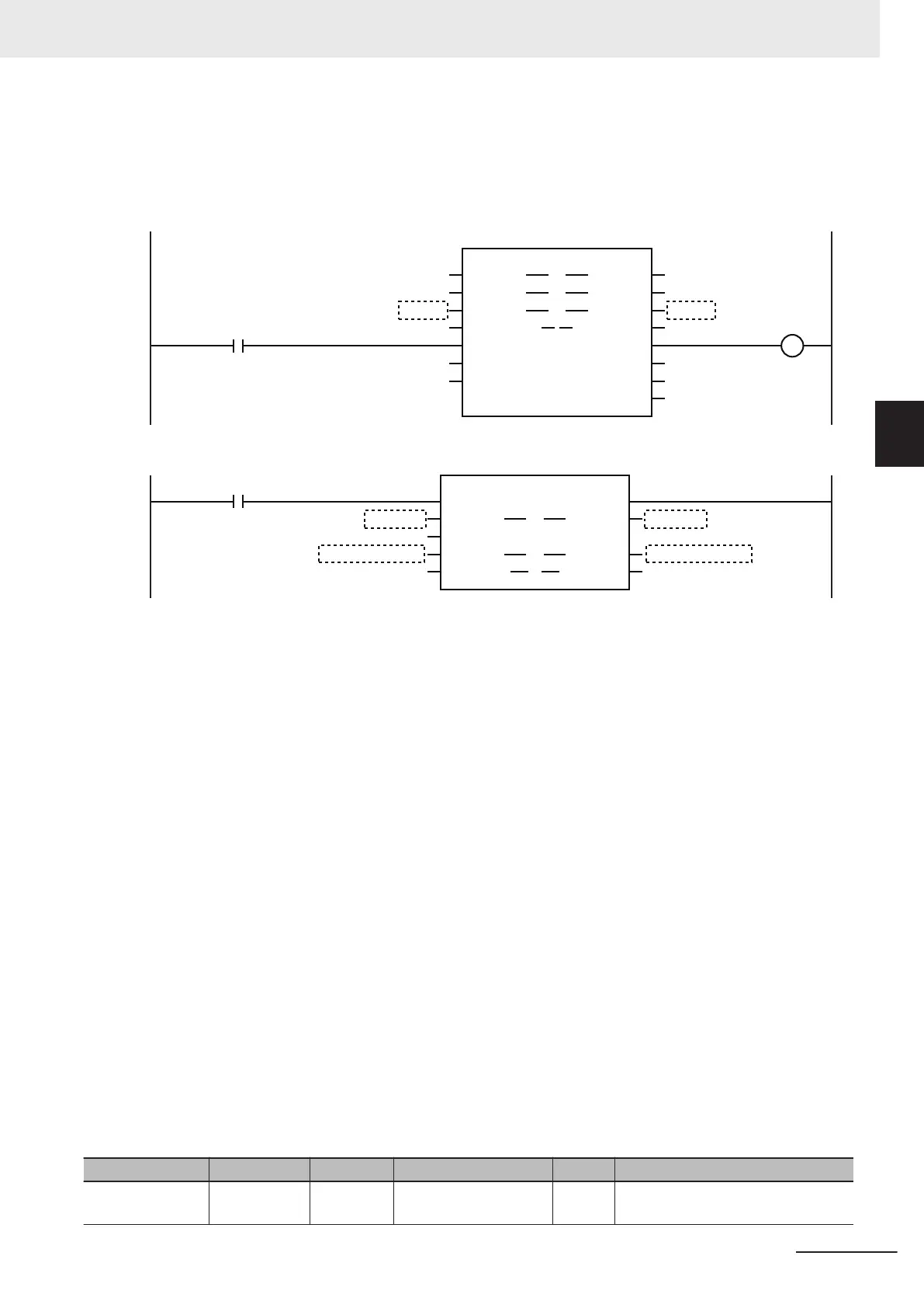
For SetDOut (Output Pulses), specify the elements of the array variable that is specified for the param-
eter for Outputs (Output Signals) in the MC_DigitalCamSwitch instruction.
For DOut (DOut Unit Output Bit), specify as the actual digital output, the device variable that is as-
signed to the output bit of the Digital Output Unit that supports time stamp refreshing.
MC_Axis001 MC_Axis001
Vel.Act
InOperation
instMC_DigitalCamSwitch
EnableMask
T
rackOptions
Axis Axis
Switches
Switches
Outputs
Outputs
Enable
Busy
ValueSource
MC_DigitalCamSwitch
TrackOptions
InOperation
Error
Outputs
TrackOptions
Outputs
TrackOptions
Switches
DCS
_Busy
DCS_Error
ErrorID DCS_ErrID
Switches
EnableMask
inst_NX_AryDOutTimeStamp1
N3_Output_Bit_00_Time_Stamp N3_Output_Bit_00_Time_Stamp
InOperation
DOut
Enable
ENO
SetDOut
SetDOut
SyncOutTime
TimeStamp
NX_AryDOutTimeStamp
DOut
TimeStamp
E001_Time_Stamp_of_Synchronous_Output
N3_Output_Bit_00 N3_Output_Bit_00
Outputs[0]
Outputs[0]
The instruction variables are described next.
Enable
• The instruction is executed while Enable is TRUE. The values in Outputs
will not change while the
variable is FALSE.
EnableMask (Enable Tracks)
• With EnableMask (Enable Tracks), you can specify whether each track is enabled or disabled when
Enable is TRUE. To turn OFF the output from the Digital Output Unit, disable the corresponding
track.
• Bit 00 corresponds to track 0 and bit 15 corresponds to track 15. The corresponding track is enabled
if a bit is set to 1 and disabled if the bit is set to 0. If you change the value of a bit from 1 to 0, the
digital output for the corresponding track will be turned OFF.
• The values that are specified in EnableMask are shown in EnableOut for the corresponding track
numbers.
Switch Structure (_sCAMSWITCH_REF Data Type)
The switch structure (_sCAMSWITCH_REF) is used to specify the ON/OFF pattern for the output sig-
nal. You can specify up to 256 ON/OFF patterns for this instruction with an array variable. You can
specify up to 16 ON/OFF patterns for one track.
The following table shows the members of the switch structure.
Name Meaning Data type Valid range Default Description
TrackNumber Track Num-
ber
UINT
0 to 15
*1
0 Specify the applicable track number.
3 Axis Command Instructions
3-421
NY-series Motion Control Instructions Reference Manual (W561)
MC_DigitalCamSwitch
3
Function