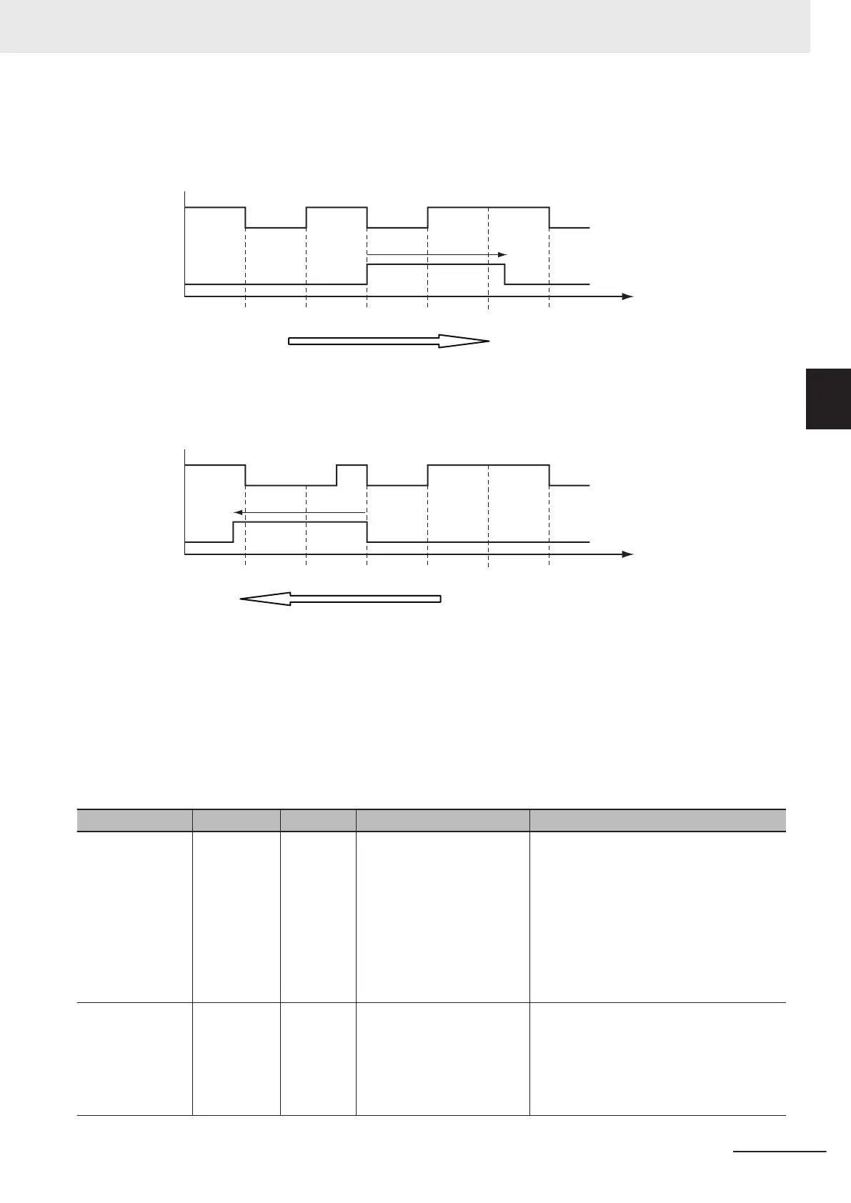
The operation is as shown below when the axis continuously rotates in the positive direction. Here, the
Count Mode is set to Rotary Mode and the ring counter range is set to 0 to 5000 in the axis
parameters.
1000.0 2000.0 3000.0 4000.0 5000.0
1,350 ms
1000.0
Track 0
Position
Switch 2 Switch 0 Switch 2
Switch 3
The axis continuously rotates in the positive direction.
Track 1
The operation is as shown below when the axis continuously rotates in the negative direction. The axis
parameter settings are the same as those that are given above.
1000.0 2000.0 3000.0 4000.0 5000.0
1,350 ms
1000.0
Track 0
Position
Switch 2
Switch 1
Switch 2
Switch 3
The axis continuously rotates in the negative direction.
Track 1
Output Signal Structure (_sOUTPUT_REF Data Type)
The output signal structure (_sOUTPUT_REF) is used to give the ON/OFF times for digital signals that
are calculated based on the switch ON/OFF pattern data. This instruction can handle up to 16 array
elements in the Outputs (Output Signals). The array element numbers in Outputs (Output Signals) in-
dicate the track numbers.
The following table shows the members of the output signal structure.
Name Meaning Data type Valid range Description
EnableOut Enable Out-
put
BOOL TRUE or FALSE Specify whether the outputs for the rele-
vant track numbers are enabled or disa-
bled.
The value of the bit for the same track
number in EnableMask
is given.
*1
TRUE: The output for the relevant track
number is enabled.
FALSE: The output for the relevant track
number is disabled.
OnTime ON Time ARRAY
[0..15] OF
ULINT
Non-negative number The time stamps at which to turn ON the
digital output are given. The time stamps
are based on the time in the NX-series En-
coder Input Unit. The value is refreshed
every task period. The unit is nanosec-
onds.
3 Axis Command Instructions
3-423
NY-series Motion Control Instructions Reference Manual (W561)
MC_DigitalCamSwitch
3
Function