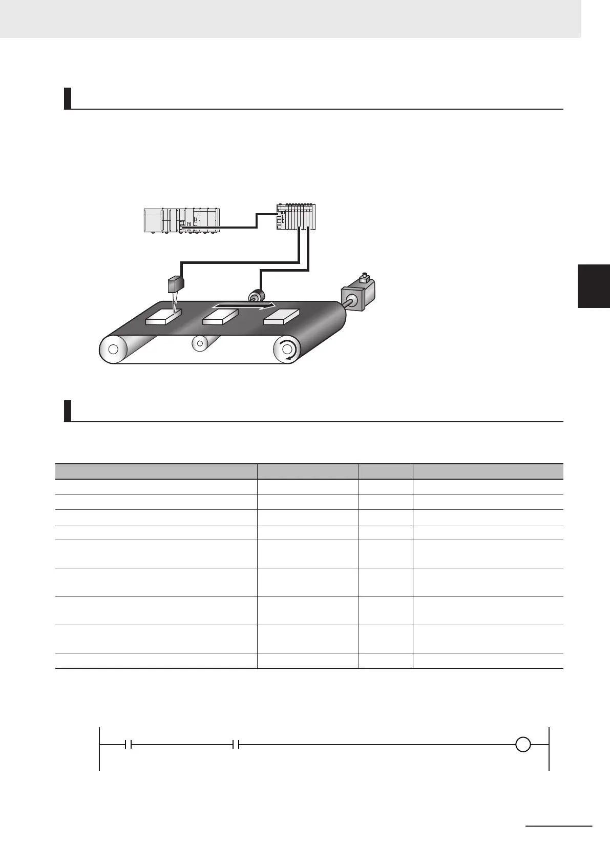
Operation Example
The sensor output turns ON when the sensor detects a workpiece. When the workpiece passes, the
sensor output turns OFF
. When the sensor detects the next workpiece, the sensor output turns ON
again.
The position of the encoder input is calculated based on the time stamp when the sensor output turns
ON. The difference between two positions is the distance between the workpieces.
Ladder Diagram
Main Variables
Name Data type Default Comment
MC_Axis000 _sAXIS_REF --- Axis Variable for axis 1.
MC_Axis001 _sAXIS_REF --- Axis Variable for axis 2.
N3_Input_Bit_00 BOOL --- Device variable
N3_Input_Bit_00_Time_Stamp ULINT --- Device variable
Position ARRAY[0..1] OF
LREAL
--- Stores the calculated positions.
Count ARRAY[0..1] OF
ULINT
--- Stores the number of rotations.
FirstPoint UINT --- A variable that is used for proc-
essing.
LastPoint UINT --- A variable that is used for proc-
essing.
Distance LREAL --- The distance between workpieces.
Sample Programming
StartPg
Lock1
MC_Axis000.D
rvStatus.Ready
If StartPg is TRUE, check that the Servo Drive for axis 1 is ready.
3 Axis Command Instructions
3-441
NY-series Motion Control Instructions Reference Manual (W561)
MC_TimeStampToPos
3
Sample Programming