b) Following Error Over Value
c) Following Error Warning Value
•
Command Position Overflow
• Command Position Underflow
Timing Charts
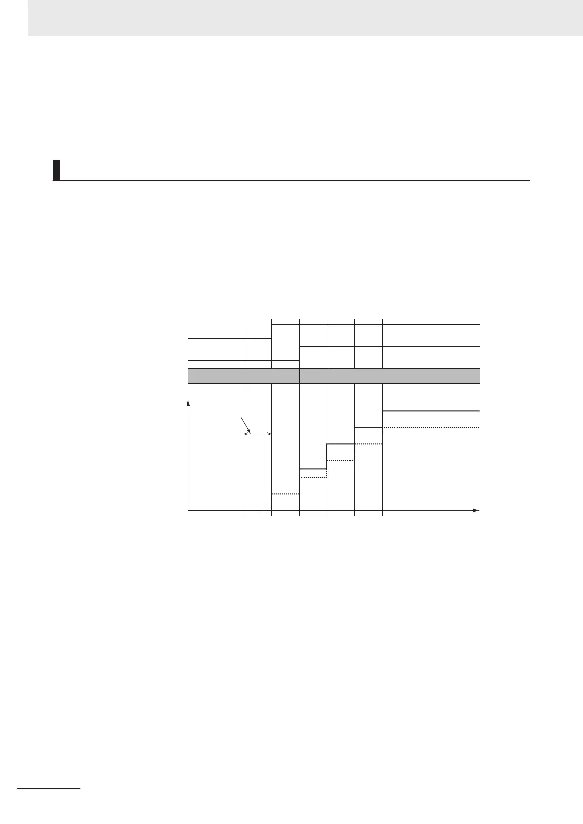
The following timing charts show when the position offset is applied when this instruction is executed.
When this Instruction Is Executed in the Primary Periodic Task
The position offset that is specified for the input is output to the Servo Drive during the next task peri-
od.
The following timing chart shows an example of the operation for when this instruction is executed in
the primary periodic task.
Active
Execute
OffsetPosition
+10
+20
+20
+20
10 20
Command position
Primary period
Solid line: After position offset is added
Dotted line: Before position offset is added
Time
MC_SyncOffsetPosition Instruction
When this Instruction Is Executed in the Priority-16 Periodic Task
The position offset that is specified for the input is output to the Servo Drive one primary period after
the next priority-16 periodic task.
3 Axis Command Instructions
3-454
NY-series Motion Control Instructions Reference Manual (W561)