Velocity (Target Velocity), Acceleration (Acceleration Rate), Deceleration (Decel-
eration Rate), and Jerk
• Set V
elocity, Acceleration, Deceleration, and Jerk to specify the interpolation velocity, acceleration
rate, deceleration rate, and jerk for linear interpolation.
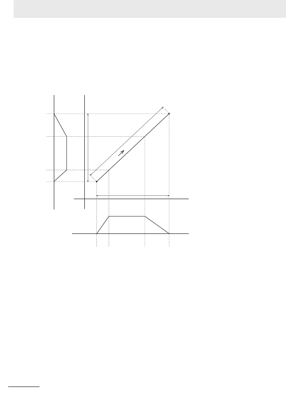
• Linear interpolation separates the interpolated motion into motion on each axis.
As an example, the following figure shows linear interpolation of 2 axes from point A to point B.
X
Td
Ta
F
B
Y
Ta
Fa0
Fa1
Td
La0
L
La1
Axis A0 motion
Axis A1 motion
A
For linear interpolation of four axes, the interpolation velocity and travel distance of each axis deter-
mine the target velocities as shown below
.
F: Specified interpolation feeding velocity
Fa0: Interpolation feeding velocity based on expansion of F to axis A0
Fa1: Interpolation feeding velocity based on expansion of F to axis A1
Fa2: Interpolation feeding velocity based on expansion of F to axis A2
Fa3: Interpolation feeding velocity based on expansion of F to axis A3
Ta: Interpolation acceleration time
Td: Interpolation deceleration time
L: Travel distance on the specified path
La0, La1, La2, and La3: Travel distances of axis A0, axis A1, axis A2, and axis A3.
L, Fa0, Fa1, Fa2, and Fa3 can be expressed with the following formulas.
4 Axes Group Instructions
4-16
NY-series Motion Control Instructions Reference Manual (W561)