EasyManua.ls Logo

Omron Sysmac NY-series User Manual

Omron Sysmac NY-series
744 pages
To Next Page IconTo Next Page
To Previous Page IconTo Previous Page
Page #99 background imageLoading...
Page #99 background image
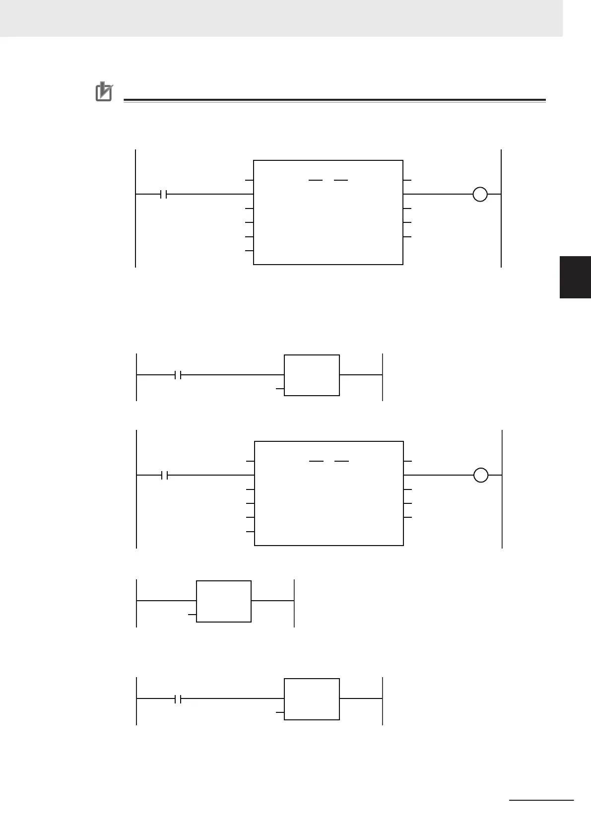
Precautions for Correct Use
When creating a ladder diagram program, you must connect the PositiveEnable (Positive Di-
rection Enable) input variable to the left bus bar and specify a variable for the NegativeEnable
(Negative Direction Enable) input variable as shown below
.
Positiv
eEnable
ErrorID
MC_MoveJog_instance
Error
MC_MoveJog
Axis Axis
Busy
CommandAbort
ed
NegativeEnable
V
elocity
Acceleration
Deceleration
MC_Axis000
POS_EN
NEGA_EN
J_ERRID
VEL
ACC
DEC
J_CA
J_ERR
J_DONE
To use the master control instructions (MC and MCR) for the MC_MoveJog (Jog) instruction,
do not program the instructions as shown below
. If you do, master control is applied only to
PositiveEnable (Positive Direction Enable), i.e., it is not applied to NegativeEnable (Negative
Direction Enable).
MC_On
MCNo
MC
In
0
Master control started.
PositiveEnable
ErrorID
MC_Mo
veJog_instance
Error
MC_MoveJog
Axis Axis
Busy
CommandAbortedNegativeEnable
V
elocity
Acceleration
Deceleration
MC_Axis000
POS_EN
NEGA_EN
J_ERRID
VEL
ACC
DEC
J_CA
J_ERR
J_DONE
MC_MoveJog Instruction
MCNo
MCR
In
0
Master control ended.
Always use the master control instructions for the MC_Power instruction.
MC_On
MCNo
MC
In
0
Master control started.
3 Axis Command Instructions
3-11
NY-series Motion Control Instructions Reference Manual (W561)
MC_MoveJog
3
Function

Table of Contents

Question and Answer IconNeed help?

Do you have a question about the Omron Sysmac NY-series and is the answer not in the manual?

Omron Sysmac NY-series Specifications

General IconGeneral
CategoryControl Unit
Operating Temperature0 to 55 °C
Power Supply Voltage24 VDC
Power Supply24 VDC
Product SeriesNY-series
CPUIntel Atom or Intel Core i7
Programming LanguagesIEC 61131-3 (LD, FBD, ST, SFC)
Memory (Program)Up to 64 MB
Ethernet Ports2
EtherNet/IP Ports2 ports (built-in)
EtherCAT Master Ports1
EtherCATYes
Motion ControlSupported
SafetyYes
Built-in I/ONo
Relative Humidity10 to 90% (non-condensing)
Vibration Resistance5 to 8.4 Hz: 3.5 mm; 8.4 to 150 Hz: 9.8 m/s²
Shock Resistance147 m/s²
Power ConsumptionVaries by model
CertificationsCE, cULus, RCM, KC, EAC

Summary

Introduction to Motion Control Instructions

Variables and Instructions

Axis Command Instructions

MC_Power

Explains the MC_Power instruction for making a Servo Drive ready to operate.

MC_MoveJog

Explains the MC_MoveJog instruction for jogging an axis according to the specified target velocity.

MC_Home

Explains the MC_Home instruction for operating the motor to determine home.

MC_HomeWithParameter

Explains the MC_HomeWithParameter instruction for setting homing parameters and operating the motor to determine home.

MC_Move

Explains the MC_Move instruction for performing absolute positioning or relative positioning.

MC_MoveAbsolute

Explains the MC_MoveAbsolute instruction for moving the axis to a specified absolute target position.

MC_MoveRelative

Explains the MC_MoveRelative instruction for moving the axis the specified travel distance.

MC_MoveVelocity

Explains the MC_MoveVelocity instruction for performing velocity control.

MC_MoveZeroPosition

Explains the MC_MoveZeroPosition instruction for positioning to an absolute position of 0.

MC_Stop

Explains the MC_Stop instruction for decelerating an axis to a stop.

MC_ImmediateStop

Explains the MC_ImmediateStop instruction for stopping an axis immediately according to the specified stopping mode.

MC_CamIn

Explains the MC_CamIn instruction to start cam operation using a specified cam table.

MC_GearIn

Explains the MC_GearIn instruction to specify the gear ratio and start gear operation.

MC_GearInPos

Explains the MC_GearInPos instruction to perform electronic gear operation with specified gear ratio.

MC_MoveLink

Explains the MC_MoveLink instruction for positioning in sync with the specified master axis.

MC_TorqueControl

Explains the MC_TorqueControl instruction to control torque using the Torque Control Mode.

MC_SetTorqueLimit

Explains the MC_SetTorqueLimit instruction to limit torque output from the Servo Drive.

MC_TouchProbe

Explains the MC_TouchProbe instruction to record axis position when a trigger signal occurs.

MC_SyncMoveVelocity

Explains the MC_SyncMoveVelocity instruction for outputting target velocity in CSV Mode.

MC_SyncMoveAbsolute

Explains the MC_SyncMoveAbsolute instruction to cyclically output target positions.

MC_Reset

Explains the MC_Reset instruction to clear axis errors.

MC_DigitalCamSwitch

Explains the MC_DigitalCamSwitch instruction to turn a digital output ON or OFF based on axis position.

Axes Group Instructions

Common Command Instructions

Related product manuals