Fieldbuses A-13
AC30 series Variable Speed Inverter
Parameter Mapping
The input and output assembly mappings of the inverter parameters are set in the parameters
3000 Input Mapping (PLC->inverter) and 3064 Output Mapping (inverter->PLC).
Parameters created in the application may be added into the mapping. The mapping of each
table ends on the first zero entry.
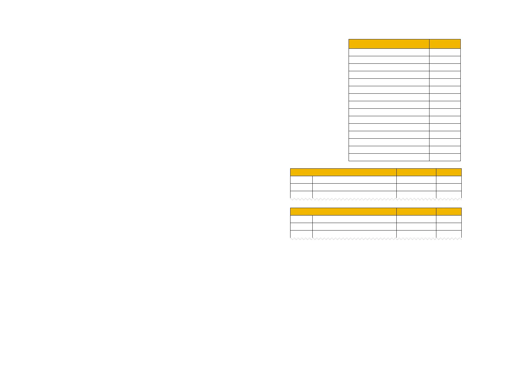
The total number of input and output
bytes mapped depends on the type of
parameters added to the mapping
tables. The number of bytes used by
each data type is summarized in the
table.
For the input mapping each parameter must be read-writable.
Parameter arrays are permitted. Configuration type parameters, string
parameters, password parameters and reserved parameters are not
permitted. The default input mapping is given in the table.
For the output mapping each parameter may be read-only or read-
writable. Parameter arrays are permitted. String parameters and
password parameters are not permitted. The default input mapping is
given in the table.
0395 Actual Speed Percent
If the input and output mappings have invalid entries then the parameter 3130 EtherNet IP State will report ERROR and the inverter will not go
into the Operational state.

 Loading...


