Fieldbuses A-35
AC30 series Variable Speed Inverter
I/O Parameter Mapping
The input and output mappings of the inverter parameters are set in the parameters
3000 Input Mapping (PLC->inverter) and 3064 Output Mapping (inverter->PLC).
Parameters created in the application may be added into the mapping. The
mapping of each table ends on the first zero entry.
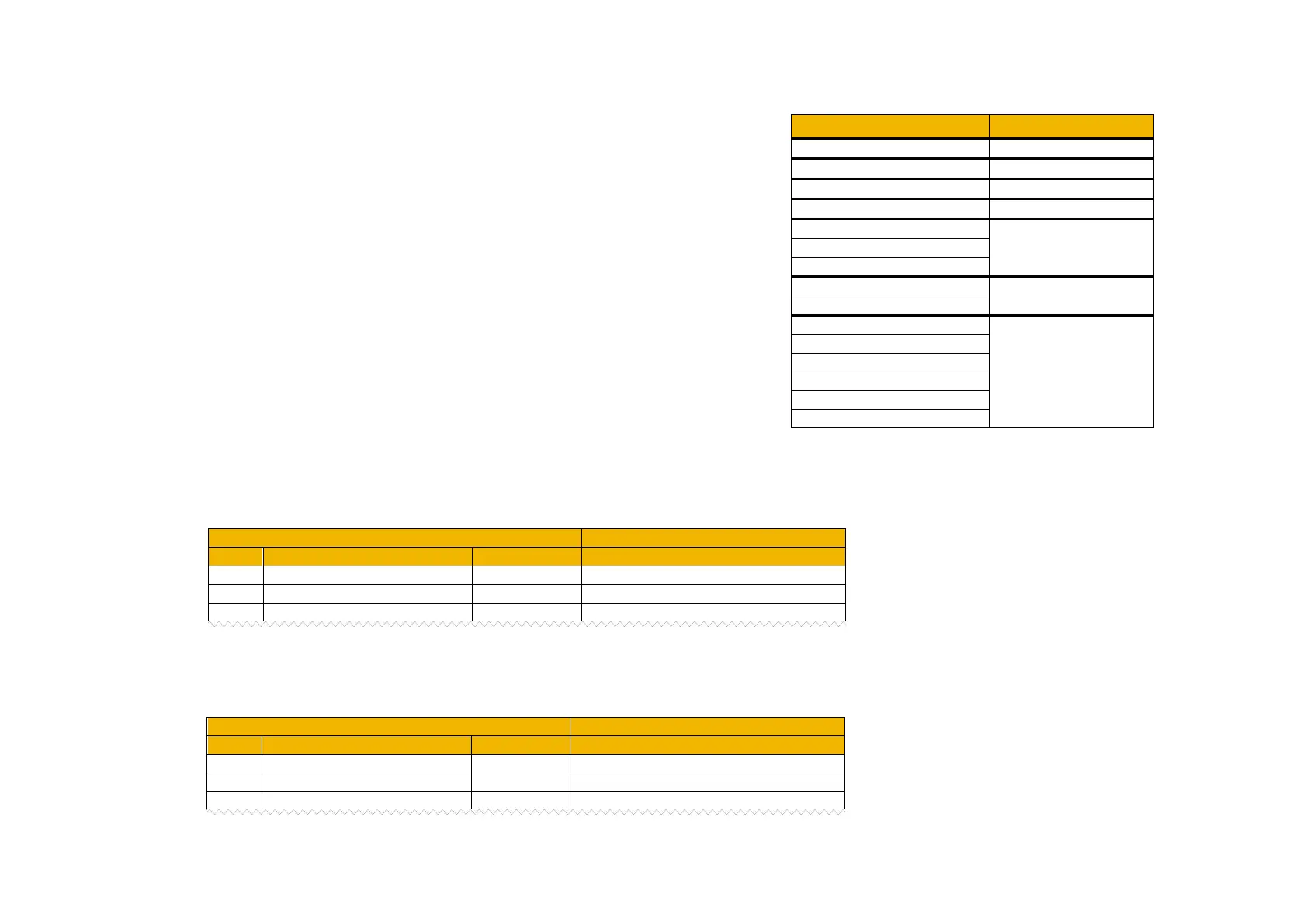
The PROFINET device and GSD file defines a number of input and output modules
that plug into the slots. The modules used depend on the type of parameter that is
being mapped. This is summarized in the table.
For the inverter input mapping (output from the PLC) each parameter must be read-writable. Parameter arrays, configuration type parameters,
string parameters, password parameters and reserved parameters are not permitted. The AC30 default input mapping is given in the table
alongside the equivalent mapping required in the PLC.
For the inverter output mapping (input to the PLC) each parameter may be read-only or read-writable. Parameter arrays, string parameters and
password parameters are not permitted. The AC30 default output mapping is given in the table alongside the equivalent mapping required in the
PLC.
PROFINET module
Unsigned8
Unsigned32
AC30 Output Mapping Table
0395 Actual Speed Percent

 Loading...


