Parameter Reference C-99
AC30 series Variable Speed Drive
Functional Description
The values associated with each terminal are shown in the IO Values parameter (D-61).
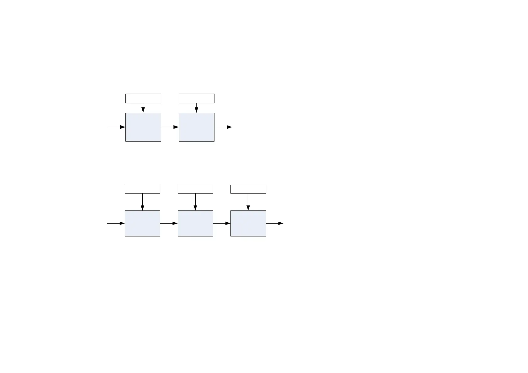
Analog input
The input signal is converted to a percentage of the selected hardware range. For the -10V…10V range the input is represented as -100 to 100%, for
all other ranges the input is represented as 0 to 100%. The Offset value is then added to this input and the result of this is multiplied by the scale
factor. The result is presented in the Value parameter.
+
Offset %
Input
0...100%
or
-100...100%
x
Scale
Value
Analog output
The output demand value is multiplied by Scale before being added to the Offset. If ABS is TRUE the absolute value of this result is used. The
output demand value is expressed as a percentage of the selected range.
x
Scale
Value %
+
Offset ABS
Demand
0...100%
or
-100...100%
|Result|

 Loading...


